Data storage device with data recovery process using fixed phase clocking for analog-to-digital conversion

a data storage device and phase clock technology, applied in the field of data storage devices, can solve the problems of corruption of written data, requiring a relatively large amount of time to re-read a sector during the data recovery procedure (drp), and achieve the effect of accurately determined

Inactive Publication Date: 2010-06-08
WESTERN DIGITAL TECH INC
View PDF13 Cites 25 Cited by
  • Summary
  • Abstract
  • Description
  • Claims
  • Application Information

AI Technical Summary

Benefits of technology

[0009]When the samples are stored in a buffer, optionally the data can be processed in the reverse direction (from end of sector to beginning of sector). The implementation of this option requires that the data in the buffer be fed into the detector in reverse order, but the Viterbi portion of the detector requires no modification since it inherently works on data processed in either direction. Reverse processing can allow recovery of data when a large defect causes a phase shift in the middle of the sector. In an alternative embodiment sync-field marks are placed at the end of the sector as well as the beginning in order to aid in processing the data in the reverse order.
[0010]The data stored in a buffer can be processed by hardware and software that are not used in normal decoding process. This allows optional analysis techniques to be used. These include fast Fourier transform (FFT) and discrete autocorrelation. Optional analysis techniques can be implemented in hardware, software or a combination of hardware and software. The frequency offset of the acquired samples can be determined accurately by analyzing the captured samples. This will allow for accurate setting of the frequency offset for sample interpolation to obtain synchronous samples.

Problems solved by technology

Unwanted variations in the amplitude, frequency, phase, resolution and overwrite properties can result in corruption of the written data.
Re-reading a sector during data recovery procedure (DRP) requires a relatively large amount of time because a full rotation of the disk is needed before the sector comes back around under the head.

Method used


Image

  • Data storage device with data recovery process using fixed phase clocking for analog-to-digital conversion
  • Data storage device with data recovery process using fixed phase clocking for analog-to-digital conversion
  • Data storage device with data recovery process using fixed phase clocking for analog-to-digital conversion

Examples


Embodiment Construction

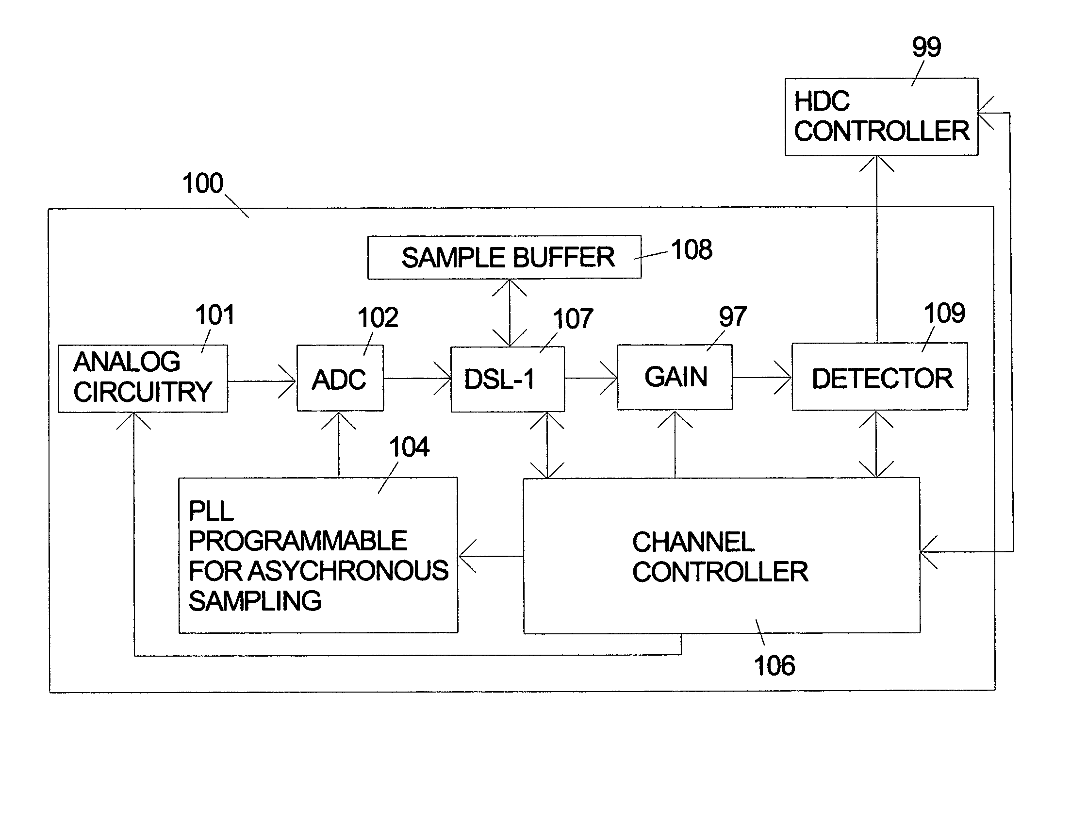
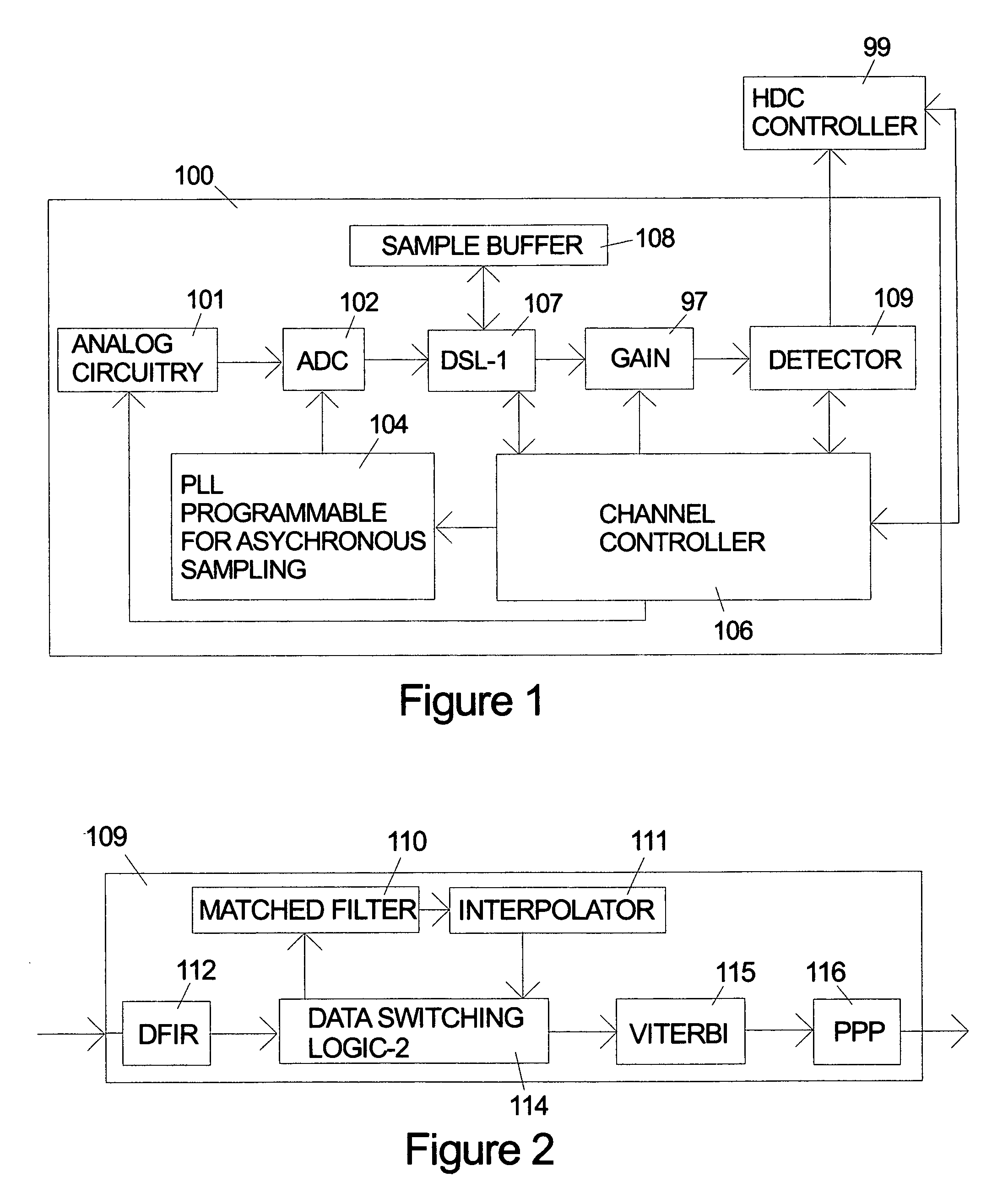
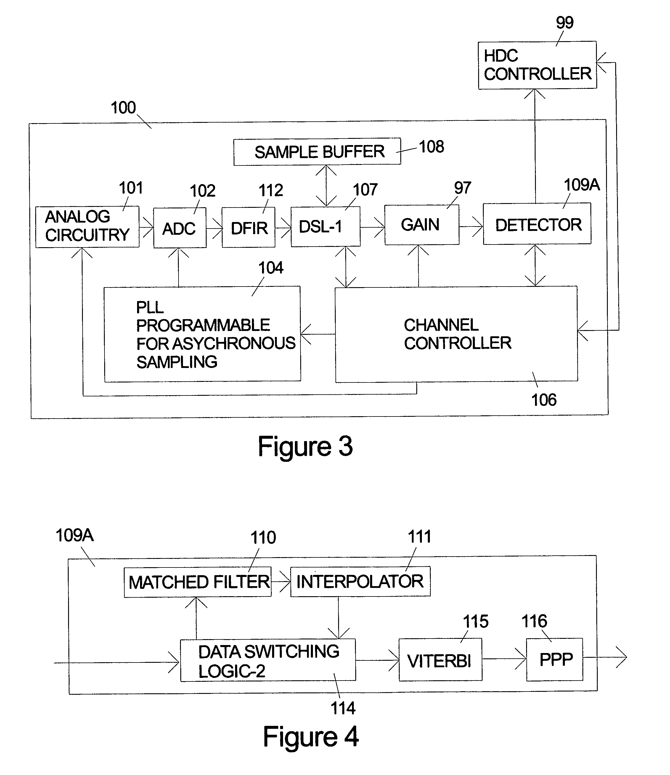
[0017]After the standard, initial error recovery attempts have failed, a data storage device typically goes into data recovery procedure (DRP) mode. A data storage device according to the invention includes data recovery procedure (DRP) that can be used in addition to any other prior art data recovery procedures. In an embodiment of the invention the DRP re-reads the analog signal for the unit of data (typically a sector) that has generated an error when processed in the standard way through the detector. Because the raw signal has unknown defects that caused the normal processing to fail, it is beneficial to limit or isolate the effects that these defects have on the decoding process. In an embodiment of the invention a fixed signal gain is used when the problem data sector is re-read in order to avoid the deleterious effects that the defects in the signal may have had on the automatic gain adjustment process that is normally used.

[0018]Another way that defects in the raw signal ca...


PUM

PropertyMeasurementUnit
voltageaaaaaaaaaa
linear phase responseaaaaaaaaaa
frequencyaaaaaaaaaa

Abstract

The invention includes apparatus and methods that allow a data storage device perform an enhanced data recovery procedure (DRP) that includes obtaining a new digital sampling of the voltages for the failing unit of data by re-reading the analog signal and converting it to digital form using an analog-to-digital conversion (ADC) using a fixed phase clock signal. The data samples are re-interpolated using a programmable delay line. The digital values representing the voltages are stored a buffer so that the data can be processed repeatedly using varying parameters as part of the data recovery procedure. Optionally the samples stored in the buffer can be processed in the reverse direction (from end of sector to beginning of sector) without requiring modification of the standard Viterbi detector since it inherently works on data processed in either direction.

Description

FIELD OF THE INVENTION[0001]The invention relates to the field of data storage devices and more particularly to apparatus and methods for recovering data when errors occur during reading of data.BACKGROUND OF THE INVENTION[0002]Data storage devices used with computers use various techniques for storing the data including optical, magnetic and optomagnetic methods. The following will focus on magnetic disk drives for simplicity, but the invention is not limited to use with magnetically stored data.[0003]Data in magnetic disk drives is recorded in concentric, radially spaced tracks arranged on the planar surfaces of one or more disks. Magnetic films on the disks are used to record bits of information in the form of magnetic domains. When operating the disks are rotated on a spindle and magnetic heads are mechanically positioned over the tracks to read and write data from the disks. Permanent servo information is typically written on the disk at the time of manufacture that allows the ...

Claims


Application Information

Patent Timeline
Patent Type & Authority Patents(United States)
IPC IPC(8): G11B5/09G11B15/52G11B19/02G11B20/18G11B5/02
CPCG11B5/09G11B20/10055G11B20/10222G11B20/10527G11B20/1403G11B20/10481G11B2020/1062
Inventor BOTTEMILLER, KRAIGGALBRAITH, RICHARD LEOHANSON, WELDON MARKOENNING, TRAVIS ROGERROSS, MICHAEL JOSEPHSAI, FUMINORI
Owner WESTERN DIGITAL TECH INC
Why Eureka
Try Eureka