
Angiographic x-ray diagnostic device for rotation angiography

a diagnostic device and angiography technology, applied in angiography, material analysis using wave/particle radiation, instruments, etc., can solve the problems of not being able to view cerebral hemorrhage, not being able to provide any treatment, and not being able to offer optimum soft tissue resolution, etc., to achieve the effect of improving the display of soft tissu

Active Publication Date: 2010-06-08
SIEMENS HEALTHCARE GMBH
View PDF37 Cites 73 Cited by
  • Summary
  • Abstract
  • Description
  • Claims
  • Application Information

AI Technical Summary

Benefits of technology

Enables visualization of small differences in soft tissue and improved 3D volume image reconstruction, reducing treatment time and eliminating the need for multiple devices by integrating correction processors within the x-ray diagnostic system, thus enhancing diagnostic accuracy and efficiency.

Problems solved by technology

The computer tomograph provides good diagnostic images of the soft tissue in question but CT devices are not able to provide any treatment due to poor patient accessibility.
The angiographic x-ray systems known to date do not offer an optimum soft tissue resolution and therefore do not allow cerebral hemorrhaging to be viewed for instance.
This results in the patient having to be transferred alley the CT examination into a room in which the angiographic x-ray examination can be carried out.
This solution is disadvantageous in that the patient still always has to be relocated and that two relatively expensive devices can be used for just one treatment.
As a rule, mobile devices do not radiate sufficient x-ray power and are thus only suited to a limited number of applications.
However, all known C-arm solutions are lacking an optimum display of capillary soft tissue.

Method used


Image

  • Angiographic x-ray diagnostic device for rotation angiography
  • Angiographic x-ray diagnostic device for rotation angiography
  • Angiographic x-ray diagnostic device for rotation angiography

Examples


Embodiment Construction

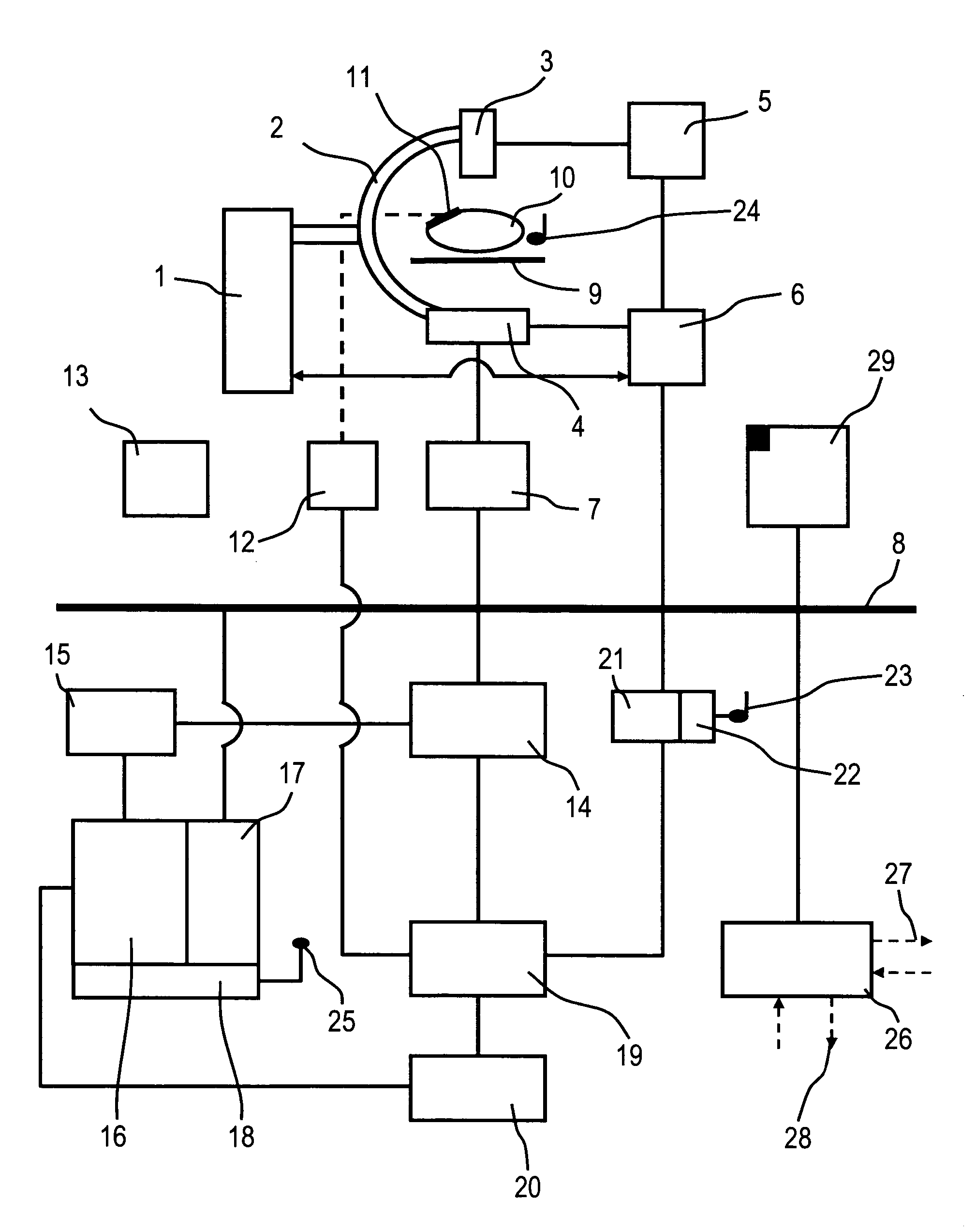
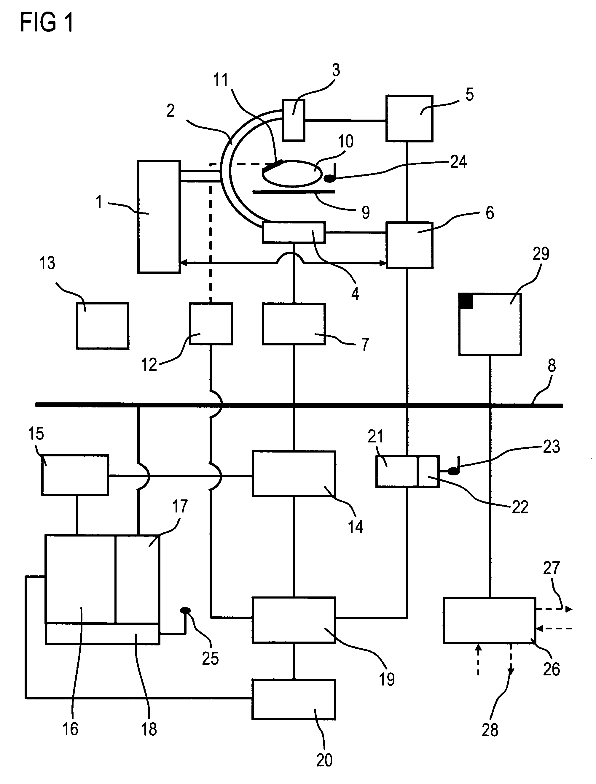
[0020]FIG. 1 shows an x-ray diagnostic device comprising a C-arm 2 which is mounted in a rotatable manner on a stand 1, at the end of which is mounted an x-ray emitter 3 and an x-ray image detector 4.

[0021]Instead of the support 1 displayed, floor and / or ceiling supports also be used. The C-arm 2 can also be replaced by a so-called electronic C-arm 2, thereby effecting an electronic coupling of the x-ray emitter 3 and x-ray image detector 4, which causes a circular path to be traveled from the x-ray emitter 3 and the x-ray image detector 4, controlled by a computing unit for instance.

[0022]The x-ray image detector 4 can be a flat, rectangular and / or square semiconductor detector which is preferably created from amorphous silicon (aSi).

[0023]A high voltage generator 5 is connected to a system controller 6 and drives the x-ray emitter 3. The system controller 6 is furthermore connected to the x-ray image detector 4, for instance the aSi flat detector, for the synchronous control of th...


PUM

PropertyMeasurementUnit
diameteraaaaaaaaaa
rotation angiographyaaaaaaaaaa
CTaaaaaaaaaa

Abstract

The invention relates to an angiographic x-ray diagnostic device for rotation angiography with an x-ray emitter which can be moved on a circular path about a patient located on a patient support table, with an image detector unit which can moved on the circular path facing the x-ray emitter, with a digital image system for recording a plurality of projection images by means of rotation angiography, with a device for image processing, by means of which the projection images are reconstructed into a 3D volume image, and with a device for correcting physical effects and / or inadequacies in the recording system such as truncation correction, scatter correction, ring artifact correction, correction of the beam hardening and / or of the low frequency drop for the soft tissue display of projection images and the 3D volume images resulting therefrom.

Description

CROSS REFERENCE TO RELATED APPLICATIONS[0001]This application claims priority to the German application No. 10 2004 057 308.5, filed Nov. 26, 2004 which is incorporated by reference herein in its entirety.FIELD OF INVENTION[0002]The invention relates to an angiographic x-ray diagnostic device for rotation angiography with an x-ray emitter which can be moved on a circular path around a patient located on a patient support table, with an image detector unit which can be revolved on the circular path facing the x-ray emitter, with a digital image system for recording a plurality of projection images by rotation angiography and with a device for image processing by means of which the projection images are reconstructed into a 3D volume image.BACKGROUND OF INVENTION[0003]One the most common diseases in the world is vascular disease, such as strokes, aneurysms or the abdominal aortic aneurysms (AAA). A rapid and safe diagnosis and the immediate introduction of treatment are of particular ...

Claims


Application Information

Patent Timeline
Patent Type & Authority Patents(United States)
IPC IPC(8): G01N23/083H05G1/02
CPCA61B6/466G06T11/005A61B6/504G06T2211/404
Inventor BRUNNER, THOMASKLINGENBECK-REGN, KLAUSMASCHKE, MICHAELNOTTLING, ALOISRUHRNSCHOPF, ERNST-PETERSCHOLZ, BERNHARDSCHREIBER, BERNDSTROBEL, NORBERT KARLWIESENT, KARLZELLERHOFF, MICHAEL
Owner SIEMENS HEALTHCARE GMBH
Learn More