Bearing apparatus having electrorheological fluid lubricant
a technology of electrorheological fluid and bearings, which is applied in the direction of shafts and bearings, rotary bearings, rolling contact bearings, etc., can solve the problems of reducing the capacity of the film to function as a lubricant-releasing agent, affecting the performance of the film, so as to reduce the viscosity facilitate the removal and replacement of the electrorheological fluid, and control the viscos
- Summary
- Abstract
- Description
- Claims
- Application Information
AI Technical Summary
Benefits of technology
Problems solved by technology
Method used
Image

Examples
example 1
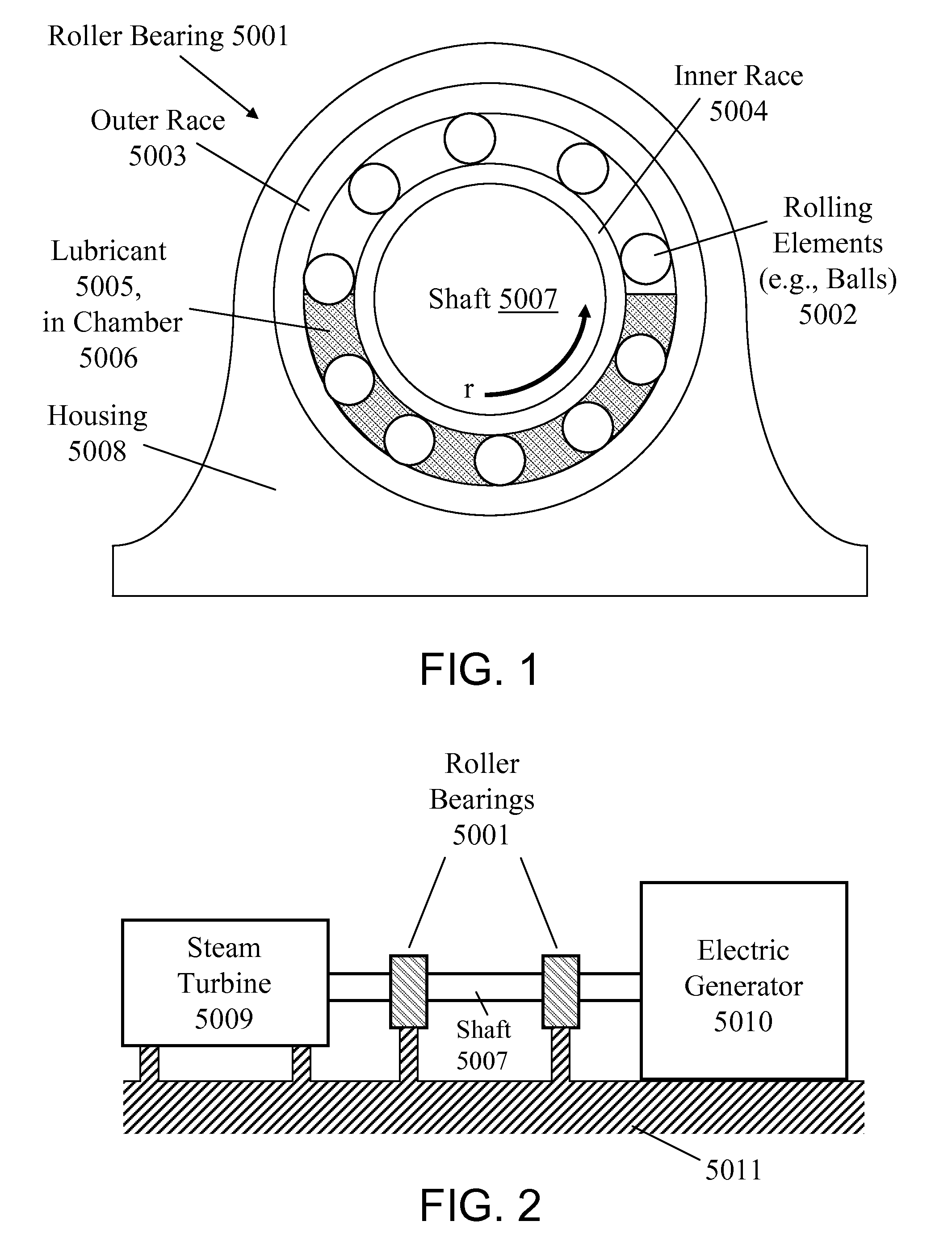
[0042]A first mode of the present invention is typically practiced so as to describe a kind of ball bearing pillow block arrangement similar to that shown in FIG. 1. According to the first inventive mode, the ERF lubricant is held in position, by means of an electric field, onto either or both of the inner and outer races. The inventive rolling element bearing apparatus is configured with two electrodes suitable for electrically holding the ER fluid in position on a raceway surface. As a rolling element moves over the raceway surface, it pushes most of the ERF lubricant out of its path, except for a thin lubricant layer that remains between the rolling element and the raceway surface. The inventive rolling element bearing is lubricated primarily by virtue of the lubricant layer coating the raceway surface.
[0043]The inventive embodiment described herein with reference to FIG. 3 and FIG. 4 involves a horizontal rotating shaft, a circular bearing element path defining a vertical geomet...
example 2
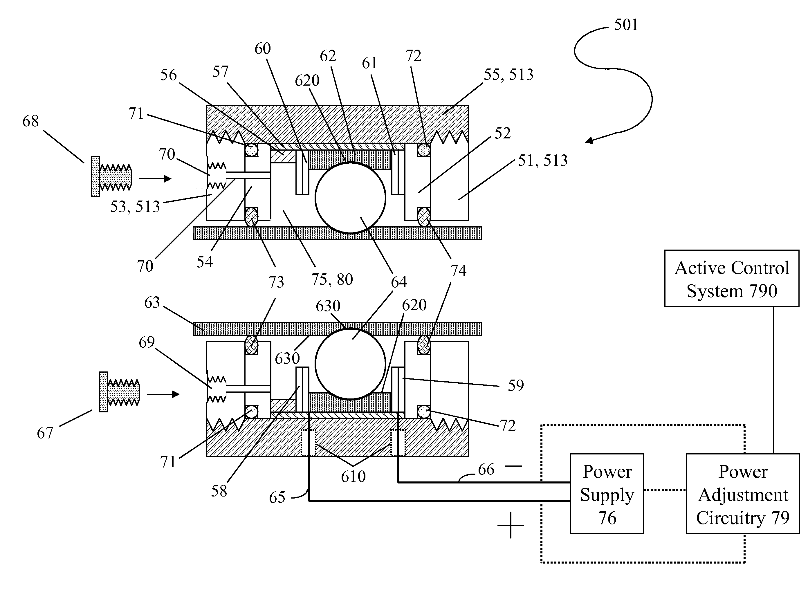
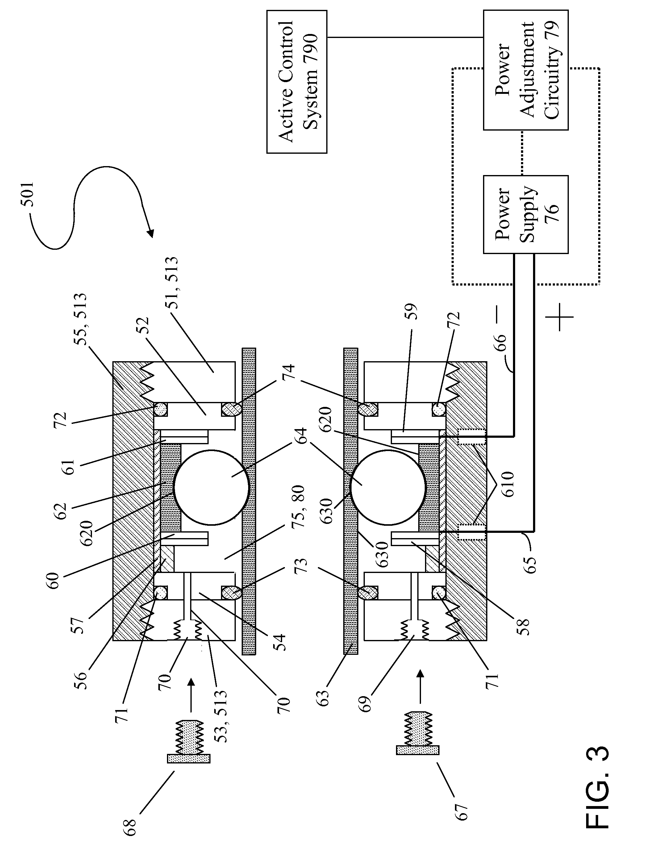
[0054]Referring now to FIG. 5 and FIG. 6, inventive ball bearing apparatus 502 includes electrically conductive outer race 62, electrically conductive inner race 63, electrically nonconductive balls 64, electrorheological fluid lubricant 80, electrically conductive retainer (spacer) 90, electrical power supply 76, electrode wires 65 and 66, and electrical connector 69. Balls 64 are spaced apart from each other by retainer 90. Balls 64 are electrically nonconductive (e.g., made of ceramic). Electrical wire 65 and electrical wire 66 (via electrical connector 69) connect power supply 76 to outer race 62 and inner race 63, respectively. As shown in FIG. 5, electrical connector 69 (e.g., a leaf spring or brush) is attached at the end of electrical wire 66 and makes electrical contact with the rotating inner race 63. Inventive ball bearing apparatus 502 also includes a fluid-tight housing, such as housing 513 shown in FIG. 3 and FIG. 4, which defines a fluid-tight chamber 75, which enclos...
example 3
[0059]First-mode inventive practice (such as exemplified by Example 1) and second-mode inventive practice (such as exemplified by Example 2) involve the so-called “Winslow effect.” According to inventive practice in which the “Winslow” effect is manifest, an electric field that is generated between two electrodes upon the electrification thereof results in the holding therebetween (i.e., between the respective electrode surfaces facing each other) of ERF fluid 80. As distinguished from Examples 1 and 2, the so-called “edge effects” are exhibited in Example 3 (which exemplifies third-mode inventive practice) and Example 4 (which exemplifies fourth-mode inventive practice).
[0060]Reference is now made to FIG. 7, FIG. 8, FIG. 9 and FIG. 10, which are illustrative of third-mode inventive practice. As shown in FIG. 7, each embedded electrode 200 is embedded in outer race 62 and has an electrode tip (longitudinally extreme edge) 201 that is even (flush) with the inward facing raceway surfa...
PUM
 Abstract
Description
Claims
Application Information