

Elevator brake and brake control circuit
- Summary
- Abstract
- Description
- Claims
- Application Information
AI Technical Summary
Benefits of technology
Problems solved by technology
Method used
Image

Examples
Embodiment Construction
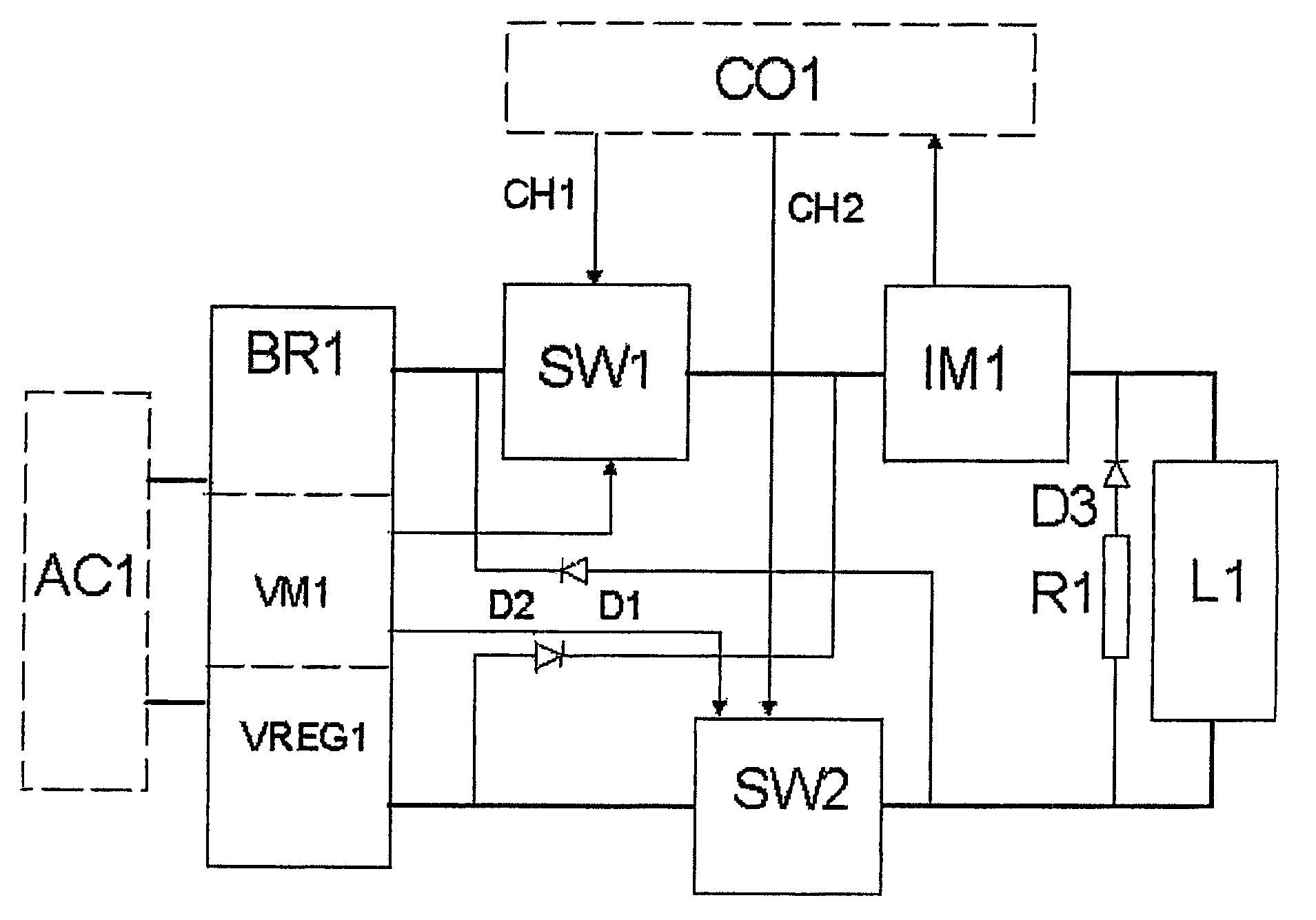
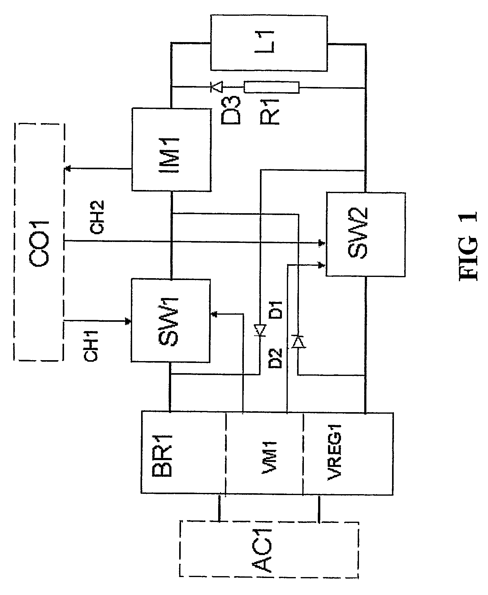
[0023]FIG. 1 represents a elevator brake control circuit, which contains a direct-current circuit comprising a brake coil L1, a rectifier bridge BR1 connected to an alternating-current network AC1, which may be e.g. a 230 V safety circuit, and semiconductor switches, e.g. IGBTs, SW1 and SW2, which are controlled by an elevator drive control unit CO1, each via a separate channel CH1 and CH2. In addition, the direct-current circuit comprises flywheel diodes D1 and D2, through which the current fed by the brake coil inductance flows when only one of the semiconductor switches is in the conducting state. In addition, the circuit comprises a series connection of a resistor R1 and a diode D3, which is connected in parallel with the brake coil L1 and through which the current generated by the large inductance of the coil L1 in a braking situation can be passed.
[0024]Moreover, the circuit comprises a direct current measuring unit IM1 producing current data, which is input to the drive contr...
PUM
 Abstract
Description
Claims
Application Information