Device and method for intraluminal imaging for the reconstruction of 3D image data sets

a technology of intraluminal imaging and image data, which is applied in the field of intraluminal imaging, can solve the problems of inability to produce such a mold, inability to accurately align individual sections of images with three-dimensional image data sets, and inability to accurately align individual sections. the effect of the mold is simpl

Inactive Publication Date: 2010-06-22
SIEMENS HEALTHCARE GMBH
View PDF8 Cites 28 Cited by
  • Summary
  • Abstract
  • Description
  • Claims
  • Application Information

AI Technical Summary

Benefits of technology

[0009]The object of the present invention consists of specifying a device and also a method for intraluminal imaging, with which in a simple manner, especially without the use of an expensive tracking system, a three-dimensional image data set of the lumen can be created.
[0011]The present device for intraluminal imaging features an imaging catheter or an imaging endoscope as its imaging instrument for recording intraluminal sectional images and a transport unit for the imaging instrument with which the imaging instrument can be pushed forwards and / or pulled back at a defined speed over a defined distance. Preferably this transport unit is a known pullback unit as is already known from the prior art in conjunction with the creation of intraluminal sectional image sequences. The outstanding feature of the present device is that a rigid, i.e. mechanically-stable singly or multiply curved guide pipe is provided, which has an internal diameter matched to the external diameter of the imaging instrument to accommodate and guide the imaging instrument and is made from a material which is transparent for the radiation used in imaging or for the waves used in imaging. The internal diameter of the opening of the guide pipe is in this case only minimally greater than the external diameter of the imaging instrument. The maximum allowed difference is produced by the maximum fault tolerances which must be adhered to for the intended intraluminal imaging. Optionally a transparent lubricant is also introduced between the inner wall of the pipe and the imaging instrument, to make it possible for the imaging instrument to move along the guide pipe with as little friction as possible.
[0013]The marking on the guide pipe is in this case preferably arranged outside the area of the lumen to be detected with the image recording, for example, on the outermost distal end of the guide pipe, but must however be able to be recorded with the imaging instrument. In another embodiment the marking is designed to be so small that it does not disturb the image information in the sectional images but is still visible. A marking which is semitransparent in respect of the imaging can also be employed. The advantage of using of one or more markings on the guide pipe compared to the fixed mechanical attachment of the guide pipe to the transport unit is that different guide pipes, i.e. guide pipes of different lengths and / or different flexibility, and / or differently curved (bent), can be used without the expense of conversion, especially for different patients or applications.
[0014]The guide pipe in the present device is designed as a pipe with a single curve or with multiple curves, to enable corresponding cavities or hollow organs to be recorded. Preferably the device comprises a number of guide pipes for different dimensions or geometries of the cavities or hollow organs, for example for different patients. Different pipes for different dimensions or geometries may thus be of different lengths, different flexibility, and differently curved (bent). In an especially advantageous embodiment, the different guide pipes feature different markings, allowing them to be distinguished on the basis of the markings. Since with the subsequent reconstruction of the 3D image data set from the individual sectional images the exact three-dimensional track of the guide pipe used in the imaging must be known exactly, this guide pipe can be identified by an evaluation unit automatically on the basis of the markings in the sectional images in order in this manner to use the correct three-dimensional track as a basis for the 3D-image reconstruction. This three-dimensional track can for example be stored in an appropriate database with the different guide pipes which can be accessed by the evaluation unit.
[0015]The use of the present device and of the associated method is restricted to applications for which a corresponding rigid guide pipe can be introduced into the hollow organ or the cavity to be recorded. The guide pipe can be introduced for applications in the body of a patient for example, endoscopically into the lumen to be recorded, as far as this is possible. The calibration of the inner ear given as an application in the introductory description represents one example, into which a suitable curved, rigid guide pipe can easily be introduced. Should the guide pipe not be sufficiently well fixed during the image recording, i.e. during the pullback, in respect of the cavity to be calibrated, an additional fixing can be undertaken. In the case of the ear this can be done in a simple manner by a fixing with special plugs, preferably featuring a close-fitting through-opening for the guide pipe and inserted into the ear.
[0020]If a non torsion-resistant imaging instrument is used, i.e. the imaging instrument is free to rotate about its longitudinal axis while in the guide pipe and being pulled back, it can be necessary to undertake the registration between the imaging instrument and the guide pipe at different positions in the guide pipe, i.e. at different pullback positions of the imaging instrument. Guide pipes with a number of markings distributed over the length of the guide pipe or one continuous marking can be used for this purpose, for example, a straight or spiral line which extends over the length of the guide pipe. This multiple registration, depending on the position at which the sectional images were recorded, means that deviations of the imaging instrument while it is being pulled back do not lead to an incorrect 3D reconstruction.

Problems solved by technology

For the three-dimensional reconstruction of cavities with a curved or wounded course from such a stack of two-dimensional sectional images however there is the problem of the individual sectional images not being able to be assembled in the correct spatial orientation to the three-dimensional image data set.
The same problem occurs for principally similar problem definitions, such as for example the use of intraluminal ultrasound, confocal microscopy and / or the use of endoscopes instead of catheters.
However the production of such a mold is very uncomfortable for the patient.
The entire process up to the point at which the three-dimensional data record is obtained, which is then used as the basis for creating the patient-individual insert, is a very complex one.

Method used


Image

  • Device and method for intraluminal imaging for the reconstruction of 3D image data sets
  • Device and method for intraluminal imaging for the reconstruction of 3D image data sets
  • Device and method for intraluminal imaging for the reconstruction of 3D image data sets

Examples


Embodiment Construction

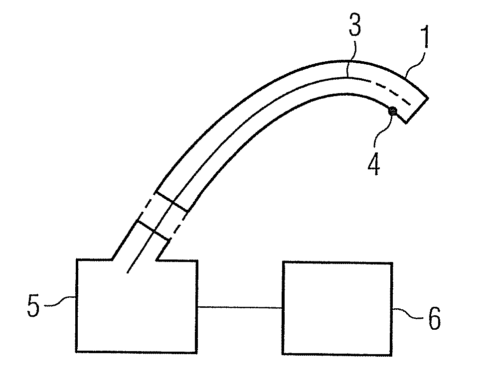
[0028]In the present example a three-dimensional image data set of the volume of the auditory canal of a patient is recorded using optical coherence tomography (OCT). This is done using an imaging catheter 3, as is known for example from U.S. Pat. No. 6,134,003 A. Details of such an imaging catheter are thus not provided in this patent application.

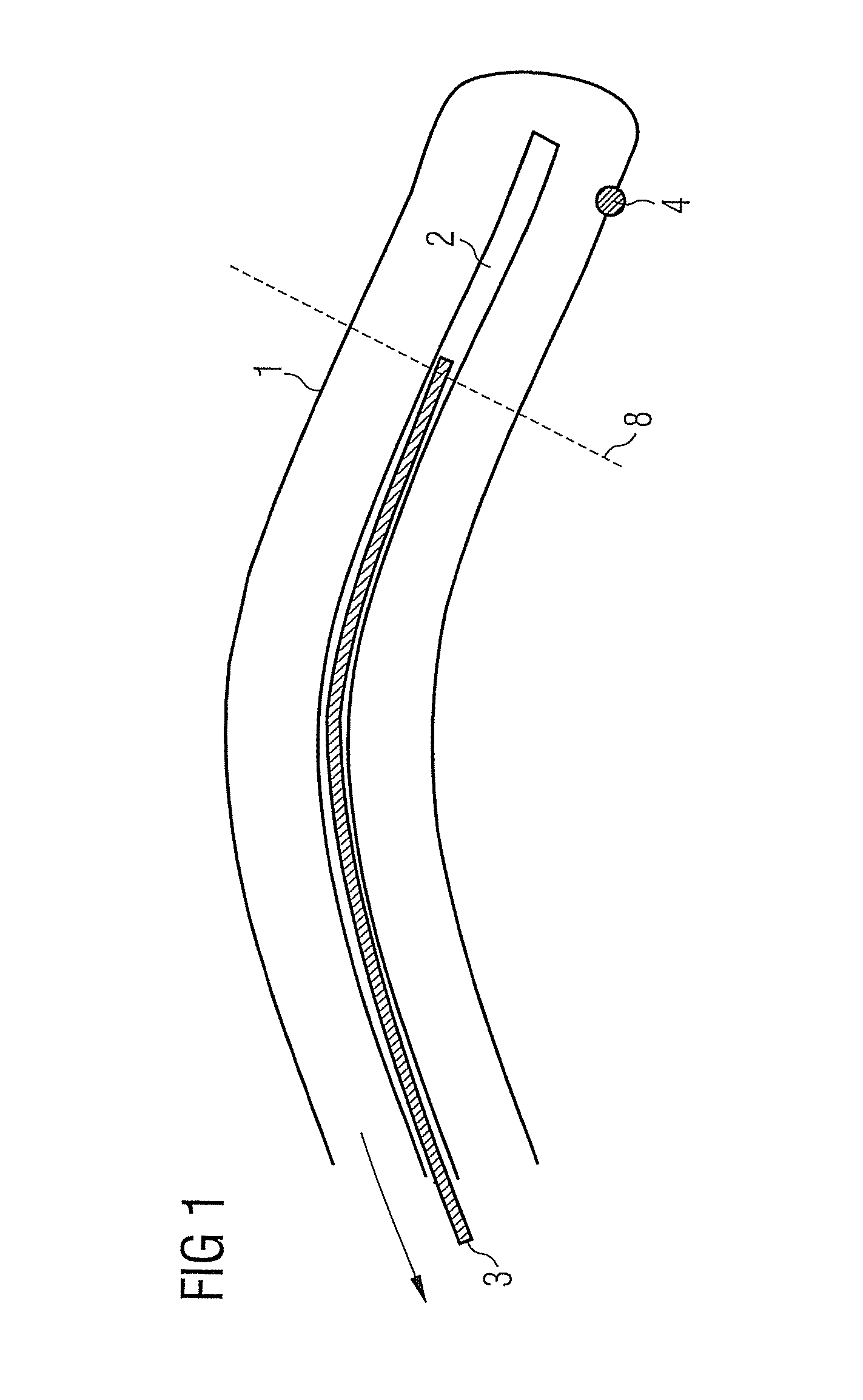
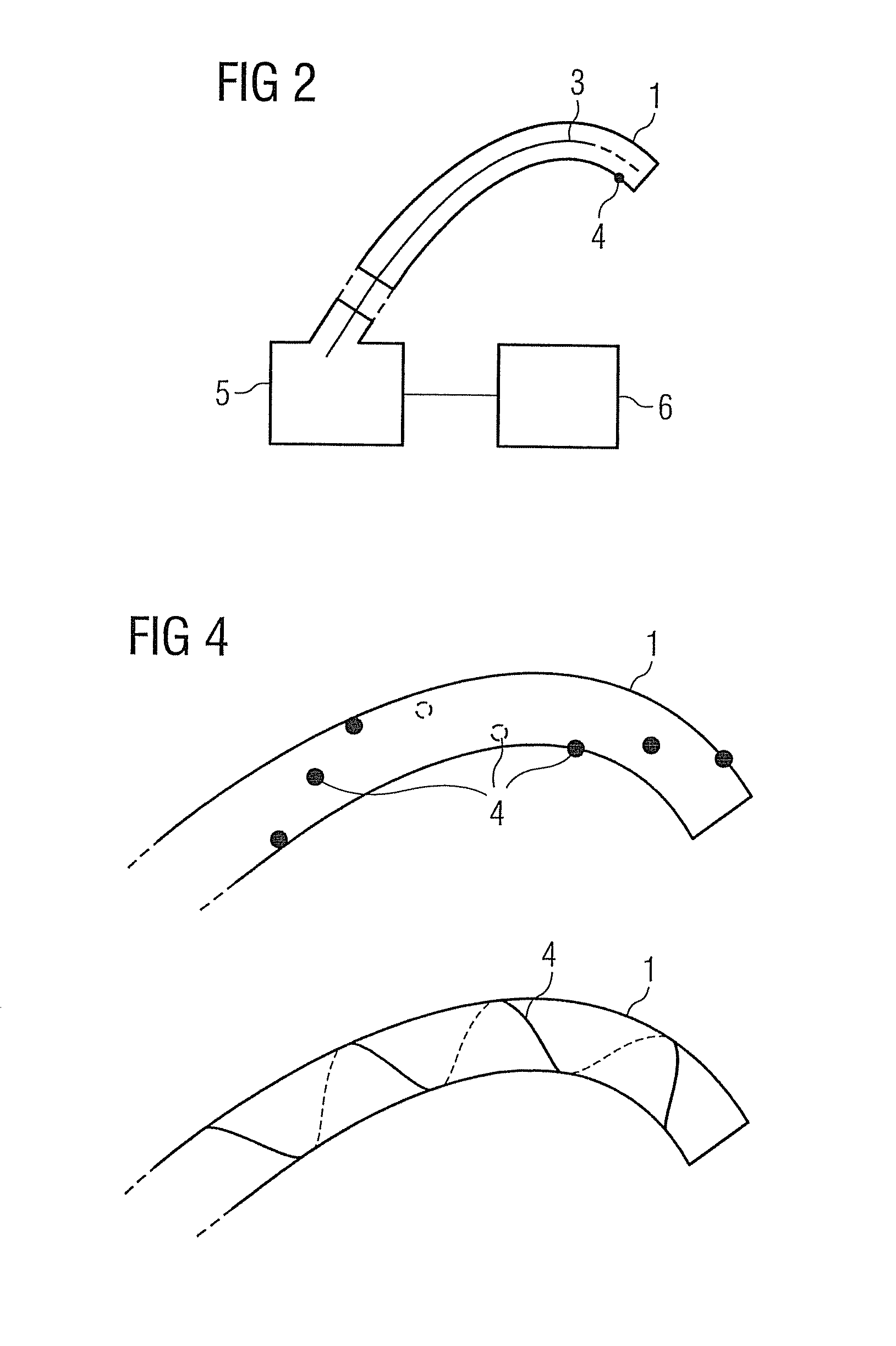
[0029]In addition to the imaging catheter 3, the present device comprises a curved, rigid guide pipe 1 with known geometry. This guide pipe 1 features, as can be seen from the cross-sectional schematic diagram in Figure, an internal channel 2 which is matched in its diameter to the external diameter of the imaging catheter 3. In the present example the guide pipe 1 is made of a plastic material transparent for optical radiation, so that imaging with the imaging catheter 3 is made possible through the guide pipe. The guide pipe 1 is closed off at its distal end. This end is provided for safety with a soft, yielding material or is made of su...


PUM


Abstract

The invention relates to a device and a method for intraluminal imaging. The device features an imaging instrument and a transport unit, with which the imaging instrument is moved in a lumen at a defined speed over a defined distance. The device further features a rigid, i.e. mechanically-stable singly or multiply curved guide pipe, which has an internal diameter matched to the external diameter of the imaging instrument to accommodate and guide the imaging instrument and is made from a material which is transparent for the radiation or to the waves used in imaging. The guide pipe features at least one marking detectable with the imaging at a known position on the guide pipe and is mechanically connectable to the transport unit. The device and the method make it possible in a simple manner to record a 3D image data set from the intraluminal recorded 2D sectional images.

Description

CROSS REFERENCE TO RELATED APPLICATIONS[0001]This application claims priority of German application No. 10 2005 030 647.0 filed Jun. 30, 2005, which is incorporated by reference herein in its entirety.FIELD OF THE INVENTION[0002]The present invention relates to a device for intraluminal imaging which comprises an imaging catheter or an imaging endoscope as an imaging instrument for recording intraluminal cross-sectional images and a transport unit for the imaging instrument with which the imaging instrument can be pushed forwards and / or pulled back in a lumen at a defined speed over a defined distance. The invention also relates to a method for intraluminal imaging with such a device.BACKGROUND OF THE INVENTION[0003]The present device, as well as the associated method, above all relate to intraluminal imaging for medical applications, but can be used in other technical areas in which tomographic imaging data is to be obtained from a cavity or a hollow body. For this type of intralum...

Claims


Application Information

Patent Timeline
Patent Type & Authority Patents(United States)
IPC IPC(8): A61B5/05
CPCA61B5/0066A61B5/6852A61B5/1076
Inventor REDEL, THOMAS
Owner SIEMENS HEALTHCARE GMBH
Why Eureka
Try Eureka