Convection glass heating furnace

a heating furnace and convection glass technology, applied in glass rolling apparatus, glass tempering apparatus, manufacturing tools, etc., can solve the problems of reducing heating efficiency, affecting heating efficiency, and heating in normal radiation mode, so as to reduce heating efficiency, reduce heating time, and eliminate defects

Active Publication Date: 2010-07-06
LANDGLASS TECH
View PDF5 Cites 3 Cited by
  • Summary
  • Abstract
  • Description
  • Claims
  • Application Information

AI Technical Summary

Benefits of technology

[0014]This invention of the furnace uses the method of ejecting high-temperature gas onto the surface of glass to heat the glass. That eliminates the defects of lower heating efficiency and longer heating time during heating glass with higher heating reflectivity and higher transparency by using the traditional furnaces. After the heating element is set inside the gas-collection box, the power of the heating element can be selected easily according to the required temperature and flow of the high-temperature gas, especially, the high-temperature gas ejecting on the upper and lower surfaces of the glass can be set to different temperature, therefore, the upper and lower surfaces of the glass is heated evenly, which ensures the heating quality.

Problems solved by technology

Because of smaller blackness of some kinds of glass, the reflectivity and transmission ratio are higher, it is not good for absorbing radiation heat, and therefore, heating with normal radiation mode has a problems of longer heating time and lower heating efficiency.
For example, in case of LOW-E, great deal of heat is reflected, the temperature on the surface of glass cannot meet requirements.
This part of conductive heat is larger than the radiation heat received on upper surface of glass, which leads to some certain temperature difference between upper and lower surfaces of the glass, causing warping at the edges of glass, and white fog occurs at the part contacting with the roller-table, and finally affecting the processing quality of glass.

Method used


Image

  • Convection glass heating furnace
  • Convection glass heating furnace
  • Convection glass heating furnace

Examples


Embodiment Construction

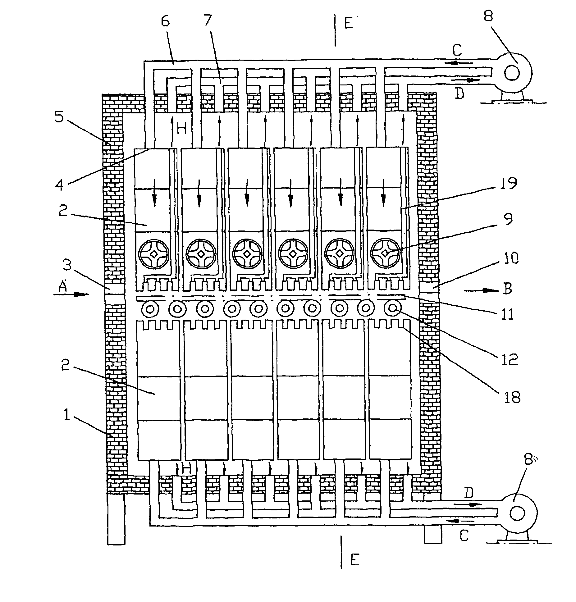
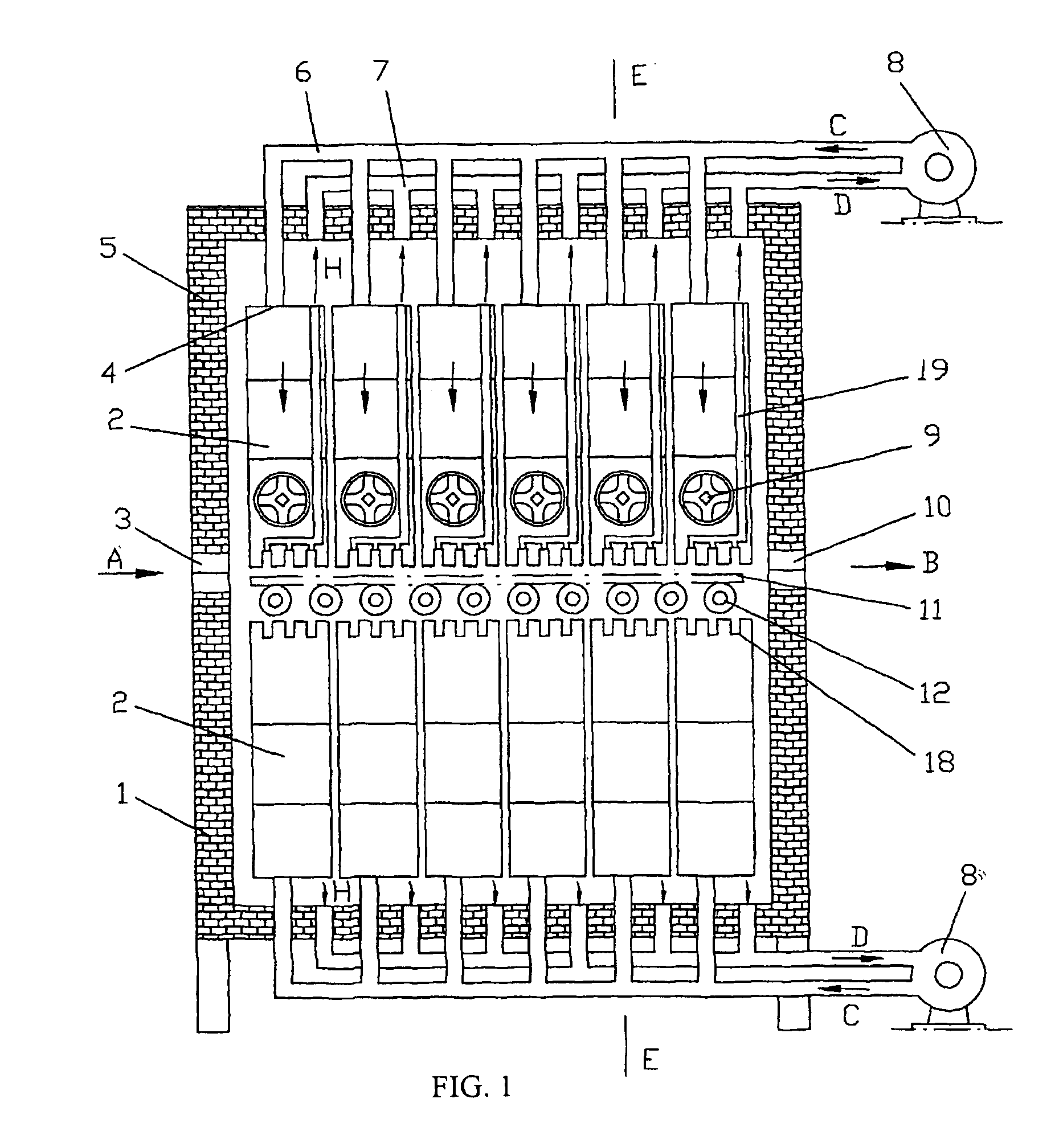
[0021]As shown in FIGS. 1 and 2, convection glass heating furnace according to the invention includes lower furnace body 1, upper furnace body 5; glass inlet 3 and glass outlet 10 are set on both side of the upper and lower furnace bodies. Glass transporting roller-table 12 is installed on lower furnace body 1. Twelve gas-collection boxes 2 are set inside the upper and lower furnace bodies respectively. The gas-collection box 2 is a sealed box on which are set gas inlet 4 and gas outlet. At the gas outlet is set a jet-flow plate 18 on which are set a lot of high-temperature gas ejecting ports 16 and exhaust gas recovery holes 17 (see FIGS. 3 and 4). The gas outlet of the gas-collection box 2 is facing the glass transportation roller-table 12, and has a certain distance to the glass transportation roller-table 12. The gas inlet 4 of the gas-collection box 2 is connected with the exhaust port of the fan 8 by pipe 6. Clip-port electric heater 9 is set in each gas-collection box 2. The ...


PUM

PropertyMeasurementUnit
reflectivityaaaaaaaaaa
transmission ratioaaaaaaaaaa
temperatureaaaaaaaaaa

Abstract

The invention disclose a convection glass heating furnace, which includes upper and lower furnace bodies, at least one gas-collection box are set in the upper and lower furnace bodies respectively, glass inlets and outlets are setup in the gas-collection box, and a jet-flow plate is set at the gas outlets. The gas inlets of gas-collection box are connected with the exhaust port of a blower fan through pipelines. Gas heating devices are setup in the gas-collection boxes. The gas inlets of the blower fan and its upstream gas routes along with the exhaust port of the blower fan and its downstream gas route form a gas circulation loop together. Glass is heated in the heating furnace of the invention by the hot gas sprayed on its surfaces, so the deficiencies of low heating efficiency and long heating time can be effectively avoided when heating the glass with high reflectivity and transmission ratio. The power of the heating devices can be expediently selected according to the temperature and the flow rate of the hot gas needed, in particular, the hot gas sprayed on the upper and under surfaces of the glass can be set to different temperatures to make the upper and under surfaces of the glass be heated uniformly and ensure the heating quality.

Description

TECHNOLOGICAL SCOPES[0001]This invention relates to a glass heating furnace, especially a heating furnace used to heat glass with complete convection method.BACKGROUND OF THE INVENTION[0002]The existing glass heating furnaces are working with radiation mode, i.e. heating glass with infrared rays emitted from resistance heating elements. Because of smaller blackness of some kinds of glass, the reflectivity and transmission ratio are higher, it is not good for absorbing radiation heat, and therefore, heating with normal radiation mode has a problems of longer heating time and lower heating efficiency. For example, in case of LOW-E, great deal of heat is reflected, the temperature on the surface of glass cannot meet requirements. In addition, when heating with radiation, roller-table transfers heat direct to the lower surface of glass. This part of conductive heat is larger than the radiation heat received on upper surface of glass, which leads to some certain temperature difference be...

Claims


Application Information

Patent Timeline
Patent Type & Authority Patents(United States)
IPC IPC(8): C03B29/00C03B29/08C03B29/12C03B29/04C03B29/06C03B27/044
CPCC03B29/08Y02P40/57
Inventor ZHAO, YAN
Owner LANDGLASS TECH
Why Eureka
Try Eureka