Display illumination device with light sensor

a technology of illumination device and light sensor, which is applied in the direction of static indicating device, lighting and heating apparatus, instruments, etc., can solve the problems of reducing detection precision, troublesome assembly and maintenance, and difficult to realize miniaturization and thinness, and achieves high precision, simplified wiring structure, and increased propagation optical path

Active Publication Date: 2010-07-06
JAPAN DISPLAY WEST
View PDF15 Cites 6 Cited by
  • Summary
  • Abstract
  • Description
  • Claims
  • Application Information

AI Technical Summary

Benefits of technology

[0015]In the light of the foregoing, it is desirable to provide an optical display device in which miniaturization, thin make, assembleness, and maintenance are improved, and luminance and a color tine are optically controlled.
[0018]In the optical display device, the reciprocating of the display lights within the light guiding plate increases the propagation optical path thereof. As a result, the display lights emitted from the respective illuminants are sufficiently mixed with one another to turn into the white display light. The light detecting sensor receives the resulting white display light, which results in the components of the white display light being detected with high precision. In the optical display device, the light detecting sensor is mounted on the same wiring board as that having the illuminants mounted thereon. Therefore, the wiring structure is simplified due to the common wiring, so that the assembly and the maintenance are improved. In addition thereto, the miniaturization, the thin make, and the cost reduction are realized. In the optical display device, the light detecting sensor may also be mounted is a space defined between the illuminants on the wiring board. In this case, the miniaturization and the thin make are realized due to the improvement in a space efficiency. In the optical display device, a light guiding protrusion portion having a suitable shape may be formed integrally with the peripheral portion of the light guiding plate in order to guide the white display light to the light receiving portion of the light detecting sensor. In this case, the suitable light detecting sensor which is not limited to the light reception specification is used, and the light receiving efficiency is also improved.
[0019]In the optical display device, for example, when the top view type light detecting sensor is used, the light guiding protrusion portion which protrudes from the peripheral portion of the light guiding plate to face the light receiving portion is formed integrally with the peripheral portion of the light guiding plate. Also, the light detecting sensor receives the white display light which leaks through the principal surface of the light guiding protrusion portion. In the optical display device, there is adopted a constriction such that an extension portion of a reflecting sheet which extends along the light guiding protrusion portion is made to face a light receiving portion of the light detecting sensor, a construction such that a total reflection surface is formed in the light guiding protrusion portion, or a construction such that a surface facing the light receiving portion is made a roughened surface. In this case, the light receiving efficiency in the light detecting sensor is enhanced, and the white display light is detected with high precision.
[0020]According to the optical display apparatus of the embodiment of the present invention, the light detecting sensor and the illuminants are mounted on the same wiring board so as to face the peripheral portion of the light guiding plate. As a result, the components are detected about the white display light which is obtained by sufficiently mixing the display lights emitted from the respective illuminants with one another in the light guiding plate. Also, the operation is controlled with high precision, so that the display is made at the optical luminance and color tone. In addition, according to the optical display apparatus of the embodiment of the present invention, the miniaturization and the thin make can be realized due to the improvement in the space efficiency and the simplification for the wiring. Also, the assembly and the maintenance are improved, and the cost reduction is realized.

Problems solved by technology

Thus, it becomes difficult to realize the miniaturization and the thin make and also it becomes troublesome to cope with the assembly and the maintenance all the more because of the independent provision of the wiring board for the LEDs and the wiring board for the optical sensor.
Thus, the optical sensor directly receives a part of the lights emitted from the respective LEDs, which results in a detection precision being reduced.
As a result, there is caused a problem such that it becomes difficult to realize the miniaturization and the thin make, and also it is troublesome to cope with the assembly and the maintenance.
On the other hand, when adopting the top view type light detecting sensor described above, the liquid crystal display device involves a problem such that a thickness increases due to a shape of the light detecting sensor, and thus the light detecting sensor has a less degree of freedom.

Method used


Image

  • Display illumination device with light sensor
  • Display illumination device with light sensor
  • Display illumination device with light sensor

Examples


Embodiment Construction

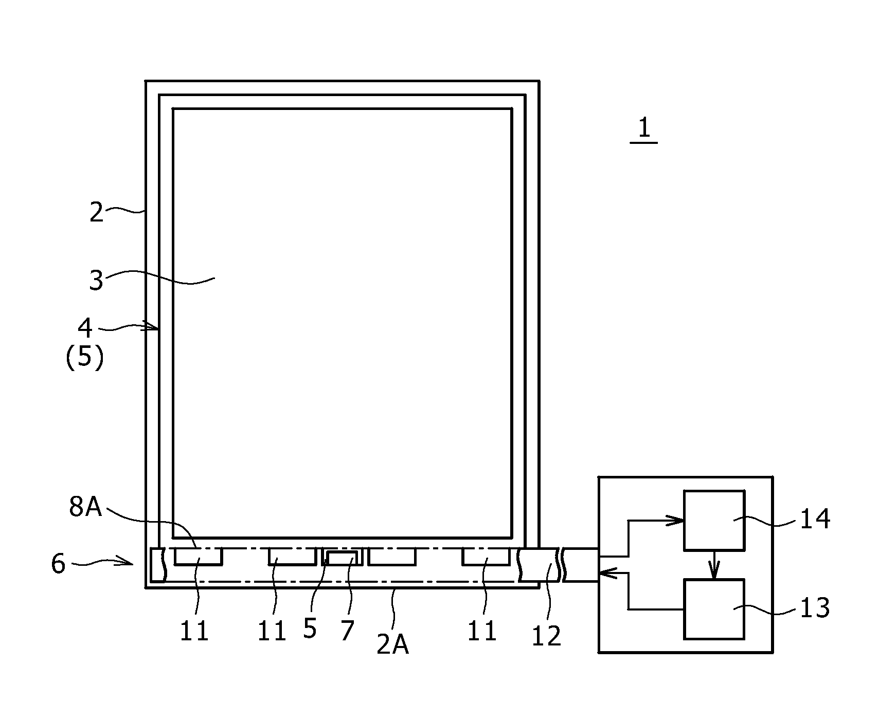
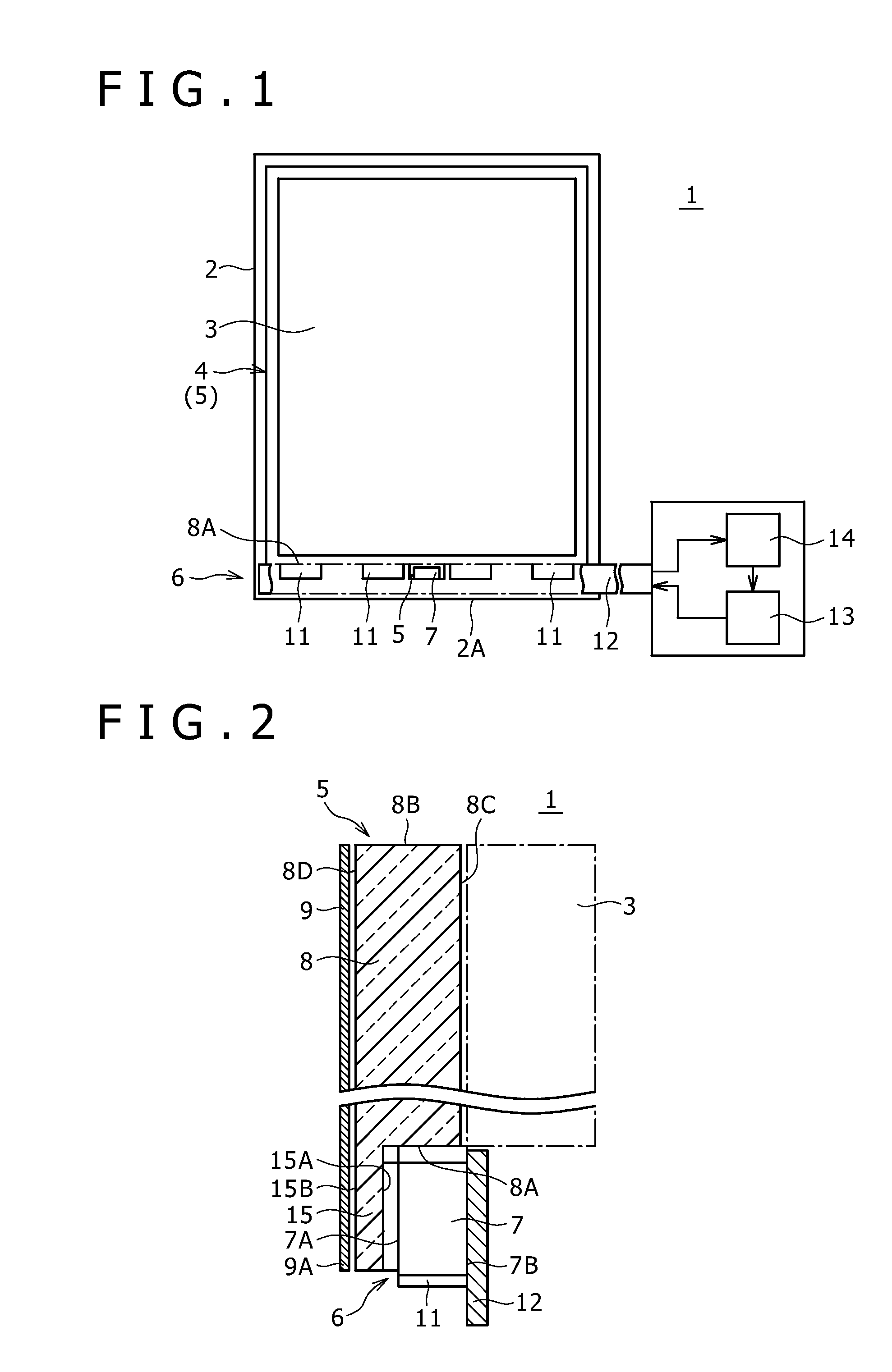
[0034]A liquid crystal display device according to a first embodiment of the present invention will be described in detail hereinafter with reference with the accompanying drawings. A liquid crystal display device 1 is similar in basic construction to the above-mentioned liquid crystal display device 100 of the related art. That is to say, as shown in FIGS. 1 and 2, a display panel unit 3 and a backlight unit 4 are assembled in a frame 2 one on top the other. While a description of details is omitted here, the display panel unit 3, for example, has a display panel. The display panel is constructed by laminating a deflecting filter, glass substrates, transparent electrodes, an orientation film, a liquid crystal, a color filter, a deflecting plate, and the like. The display panel unit 3 is assembled in the frame 2 with its peripheral portion being fixed.

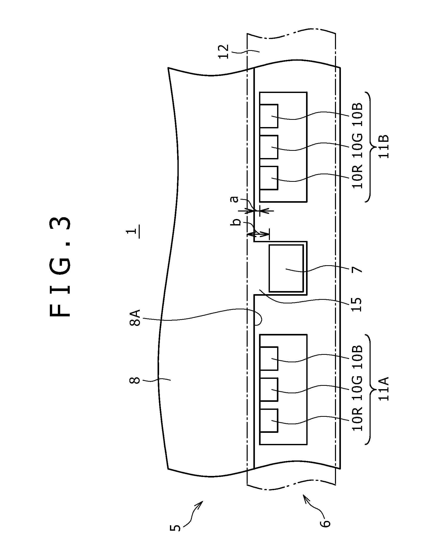
[0035]In the liquid crystal display device 1, the backlight unit 4 has a display light guiding optical unit 5, a light emitting porti...


PUM


Abstract

An optical display device, including a light guiding plate, a light detecting sensor and at least two illuminants. The light detecting sensor and the illuminants are commonly mounted on a wiring board with the at least two or more illuminants disposed to face a light incidence surface of the light guiding plate. The light detecting sensor is disposed on the same side of the wiring board as the illuminants with respect to the light guiding plate.

Description

CROSS REFERENCE TO RELATED APPLICATIONS[0001]The present invention contains subject matter related to Japanese Patent Application JP 2006-059995 filed in the Japanese Patent Office on Mar. 6, 2006, the entire contents of which being incorporated herein by reference.BACKGROUND OF THE INVENTION[0002]1. Field of the Invention[0003]The present invention relates to a transmission type liquid crystal display device and various types of optical display devices for guiding color display lights emitted from a light emitting portion having at least two or more illuminants having different peak wavelengths, for example, a red illuminant, a green illuminant, and a blue illuminant to a display portion through a light guiding plate provided on a back face side of the display portion in order to perform color display.[0004]2. Description of the Related Art[0005]For example, in a transmission type or semi-transmission type liquid crystal display device, a back face of a display panel unit having a ...

Claims


Application Information

Patent Timeline
Patent Type & Authority Patents(United States)
IPC IPC(8): F21V7/00F21V9/08
CPCG02B6/0068G09G3/3413G02B6/0018G02B6/0021G02B6/0073G09G3/3611G09G2360/145G02F1/133G02F1/1335
Inventor YOSHINO, KOJIKIMURA, SUSUMUSUZUKI, HIROMASA
Owner JAPAN DISPLAY WEST
Why Eureka
Try Eureka