
Fusion splicing structure of optical fibers

a technology of optical fibers and splicing structures, applied in the direction of optical fibres with multi-layer cores/claddings, optical waveguide light guides, instruments, etc., can solve the problems of increased reliability, and damage to coated portions by large signal loss, so as to prevent the deterioration of fiber coatings and prolong the service life. , the effect of improving reliability

Inactive Publication Date: 2010-07-06
FUJIKURA LTD
View PDF21 Cites 33 Cited by
  • Summary
  • Abstract
  • Description
  • Claims
  • Application Information

AI Technical Summary

Benefits of technology

The present invention provides a fusion splicing structure for optical fibers that prevents deterioration of the fiber coating and increases the reliability of the splicing. The structure includes a block made of a highly thermal conductive material that covers the fusion splicing point of the double clad fiber and the single clad fiber. The block has a refractive index higher than that of the claddings and is coated with a resin that has a high light transmittance. The resin may also have an infrared-ray absorbing layer. The structure may also include an infrared-ray absorbing material on the block to prevent the leakage of excitation light. The use of a hard resin for adhering one of the fibers and a rubber-type resin for fixing the other fiber reduces tension on the fibers and allows them to follow the expansion and contraction of the metal. The resin for coating the first clad fiber in front of the fusion splicing point has a higher refractive index than the cladding and an infrared-ray absorbing layer.

Problems solved by technology

Thus, generally used coating materials may be discolored or burnt when used for a prolonged time, which contributes to a decrease in reliability.
Therefore, there is a possibility that a reinforcement resin in contact with this point may burn, and the reinforcement resin and a coating is not brought closer to the fusion splicing point.
A great signal loss may damage a coated portion.
Since signal beams are fewer in NA, there is a case where a coating at the side of the proximal end several millimeters to several dozen millimeters from a fusing point may be damaged.

Method used


Image

  • Fusion splicing structure of optical fibers
  • Fusion splicing structure of optical fibers
  • Fusion splicing structure of optical fibers

Examples


first embodiment

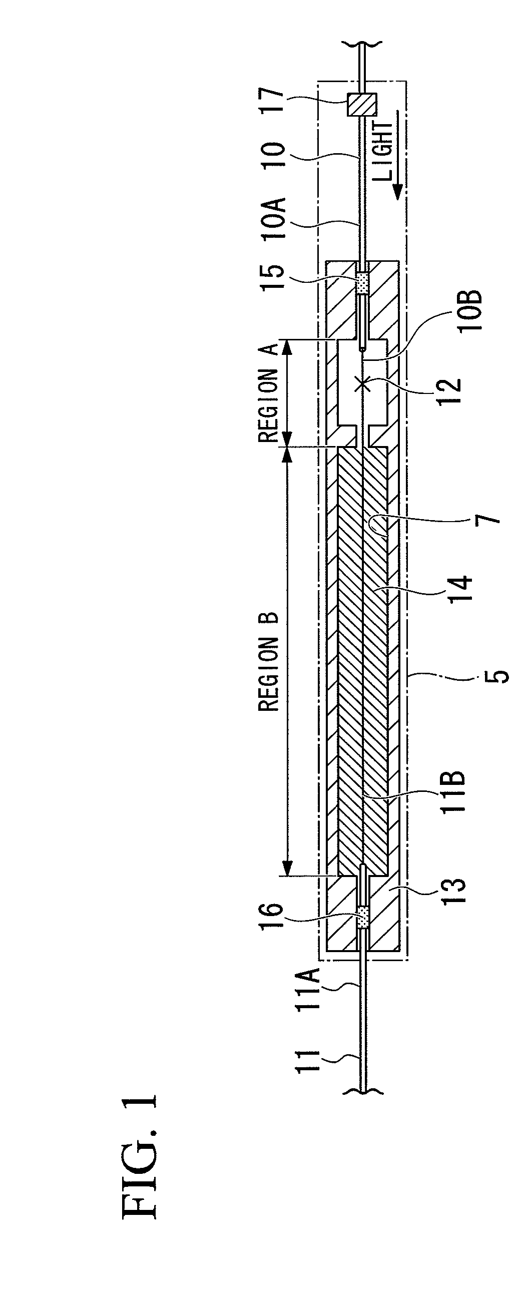
[0039]FIG. 1 shows First Embodiment of the fusion splicing structure of optical fibers of the present invention.

[0040]FIG. 1 shows a double clad fiber 10, a single clad fiber 11, an aluminum block 13 covering a fusion splicing point 12 of the double clad fiber 10 and the single clad fiber 11, and a resin 14 filled into the aluminum block 13. A coating 10A and a coating-removed portion 10B are formed on the double clad fiber 10, and first and second clads to be described later are exposed at the coating-removed portion 10B. A coating 11A and a coating-removed portion 11B are formed on the single clad fiber 11, and a clad to be described later is exposed at the coating-removed portion 11B. The distal end of double clad fiber 10 and that of the single clad fiber 11 are subjected to a fusion splicing for the respective clads at the fusion splicing point 12. The double clad fiber 10 is adhered to the aluminum block 13 at a first adhesion portion 15, and the single clad fiber 11 is adhere...

second embodiment

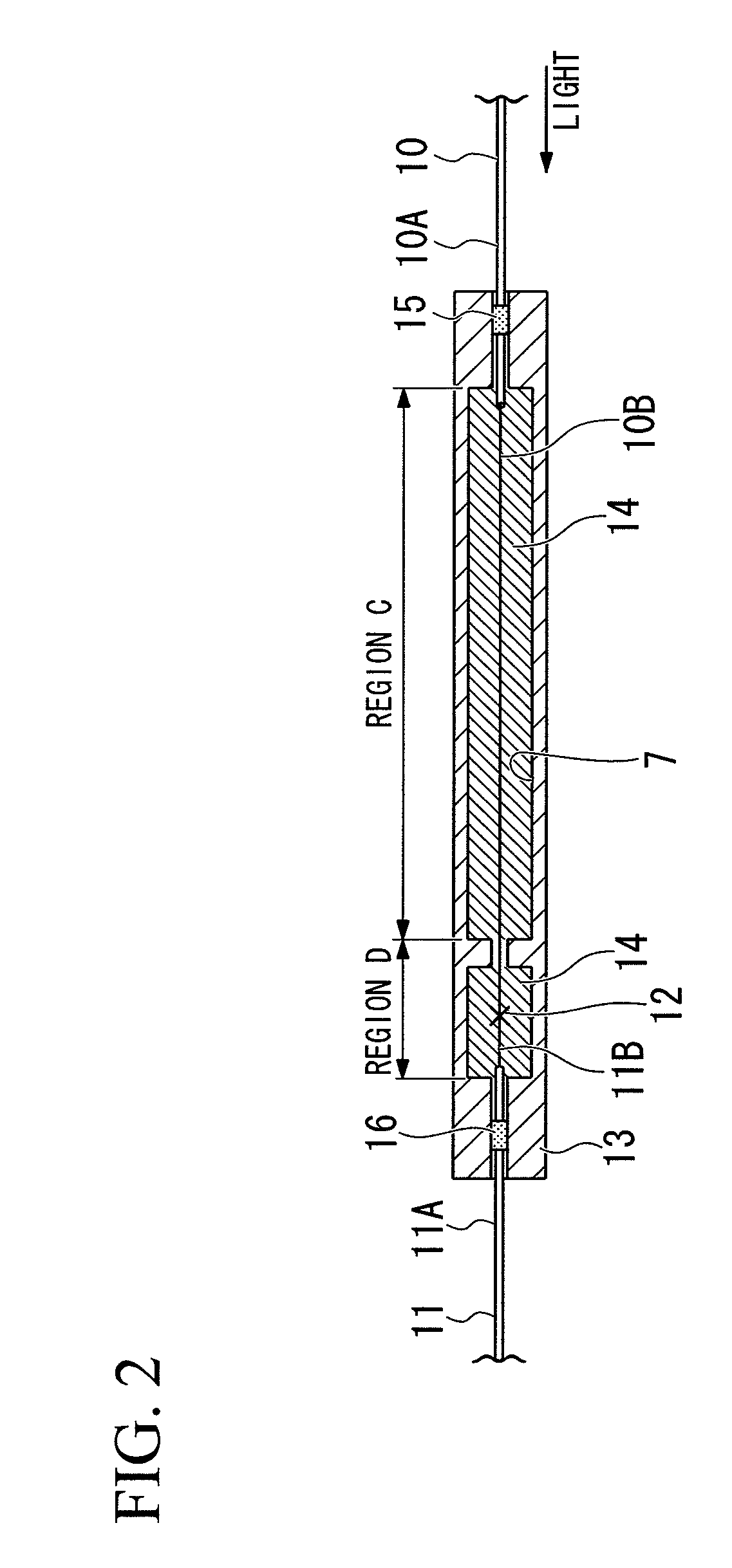
[0057]FIG. 2 shows Second Embodiment of the fusion splicing structure of optical fibers of the present invention. The fusion splicing structure of optical fibers of the present embodiment includes the same constituents as those used in the splicing structure of First Embodiment, and the same numerals or symbols are given to the same constituents.

[0058]In the fusion splicing structure of optical fibers of the present embodiment, a coating-removed portion 10B in which the first clad of the double clad fiber 10 is exposed is accommodated inside the aluminum block 13 at a region C in front of the fusion splicing point 12 (on the double clad fiber). The coating-removed portion 10B is coated with the resin 14 higher in refractive index than the first clad, and the resin 14 is also enclosed by the aluminum block 13 in which black alumite functioning as the infrared-ray absorbing layer 7 is formed internally.

[0059]Further, at a region D in the vicinity of the fusion splicing point 12, the f...

third embodiment

[0062]FIG. 3 shows Third Embodiment of the fusion splicing structure of optical fibers of the present invention. The fusion splicing structure of optical fibers of the present embodiment includes the same constituents as those used in the splicing structure of First Embodiment, and the same symbols are given to the same constituents.

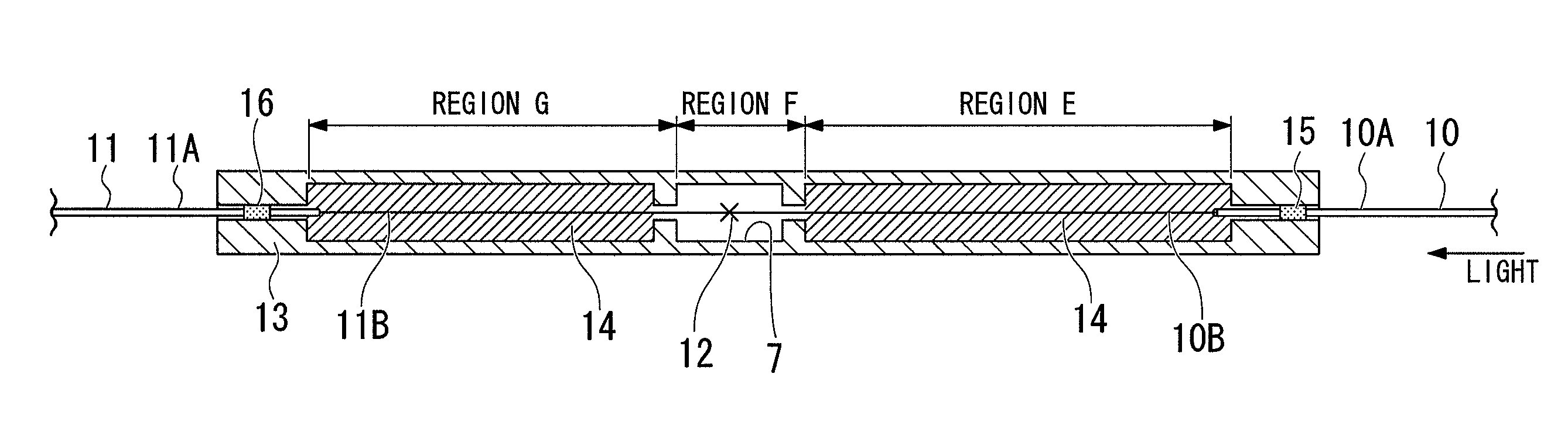
[0063]In the fusion splicing structure of optical fibers of the present embodiment, excitation light is emitted in a stepwise fashion along the longitudinal direction of the aluminum block 13 at three regions, that is, a region E at the side of the double clad fiber 10 from the fusion splicing point 12, a region F having the fusion splicing point 12 and a region G at the side of the single clad fiber 11 from the fusion splicing point 12, thereby diversifying heat-generating regions.

[0064]The resin 14 to be filled into the region E is lower in refractive index than the clad, and also smaller in NA than the first clad of the double clad fiber 10 through wh...


PUM

PropertyMeasurementUnit
light wavelengthaaaaaaaaaa
light transmittanceaaaaaaaaaa
refractive indexaaaaaaaaaa

Abstract

The present invention is a splicing structure of optical fibers for fusing a double clad fiber and a single clad fiber, the splicing structure is provided with a block covering a fusion splicing point of the double clad fiber and the single clad fiber, and which is made of a highly thermal conductive material.

Description

CROSS-REFERENCE TO RELATED APPLICATIONS[0001]The present application claims the right of priority to the Japanese Patent Application No. 2007-129034 filed on May 15, 2007 and the Japanese Patent Application No. 2007-257507 filed on Oct. 1, 2007, the content of which is incorporated herewith by reference.BACKGROUND OF THE INVENTION[0002]1. Field of the Invention[0003]The present invention relates to a fusion splicing structure of a rare earth-added double clad fiber and a single clad fiber for light amplification used in optical fiber amplifiers and optical fiber laser light sources, and in particular to a fusion splicing structure which can be increased in service life of a fiber coating material and greatly improved in reliability by managing appropriately the heat dissipation at a fusion splicing point.[0004]2. Description of Related Art[0005]In optical fiber amplifiers and optical fiber laser light sources, a double clad fiber is used as optical fibers for light amplification. Th...

Claims


Application Information

Patent Timeline
Patent Type & Authority Patents(United States)
IPC IPC(8): G02B6/255
CPCG02B6/2558
Inventor OBA, YASUHIRO
Owner FUJIKURA LTD
Learn More