Plate type catalytic reactor

a catalytic reactor and plate-type technology, applied in the direction of liquid-gas reaction process, machine/engine, chemical/physical/physical-chemical stationary reactor, etc., can solve the problems of catalyst damage, insufficient removal of heat generated by the reaction, and restriction of the heat transfer medium to be supplied to the shell sid

Active Publication Date: 2010-07-06
MITSUBISHI CHEM CORP +1
View PDF18 Cites 9 Cited by
  • Summary
  • Abstract
  • Description
  • Claims
  • Application Information

AI Technical Summary

Benefits of technology

[0020]The present invention relates to a new plate type catalytic reactor to solve the above-mentioned problems, and it has the following features.

Problems solved by technology

However, there is restriction on the heat transfer medium to be supplied to the shell side because it is necessary to elevate the temperature to around 600° C.
However, the temperature profile in a catalyst layer in a reaction tube is such that in the reaction region in the vicinity of the inlet of reaction tube where the reactivity is large, the removal of heat generated by the reaction is insufficient and the heat is accumulated in the catalyst layer to elevate the temperature of the catalyst layer.
In the extreme case, the catalyst is damaged due to a high temperature.
In a case of oxidation reaction accompanying an extremely large heat, there was the problem that the temperature of the catalyst layer was very high in, in particular, the reaction region in the vicinity of the catalyst layer inlet, hence, a hot spot being easily formed.
The hot spot in the catalyst layer elevates the temperature at the surface of the catalyst to accelerate the deterioration of the catalyst in this reaction region and reduces the selectivity of reaction, whereby the yield of the product decreased.
Further, it is difficult to mix quickly at the shell side the supplied heat transfer medium having different temperatures with the heat transfer medium circulated in the reactor.
This brings further non-uniformity of the heat transfer medium temperature at the shell side of the reactor.
When the catalysts in the reaction tube are to be replaced by new ones, much labor and a long time are needed to replace the catalysts.
This caused a large pressure loss in a starting material gas passed through the catalyst layer.
In particular, in an oxidation reaction, there was the problem of increasing power for a blower or a compressor necessary to compress molecular oxygen-containing gas such as air.

Method used


Image

  • Plate type catalytic reactor
  • Plate type catalytic reactor
  • Plate type catalytic reactor

Examples


example 1

[0106]In preparing acrylic acid by the oxidation of propylene with molecular oxygen, a catalyst powder having a composition of Mo12Bi5Ni3Co2Fe0.4B0.4K0.1Si24Ox was prepared as a first stage catalyst. The catalyst powder was molded to obtain a ring-shaped catalyst having an outer diameter of 5 mmΦ, an inner diameter of 2 mmΦ and a height of 4 mm.

[0107]Similarly, a catalyst powder having a composition of Sb100Ni43Mo35V7Nb3Cu9Si20Ox was prepared as a second stage catalyst. With the catalyst powder, a ring-shaped catalyst having the same shape as the first stage catalyst was prepared. In the above-mentioned compositions, (x) indicates a value given by the oxidation state of each metal oxide.

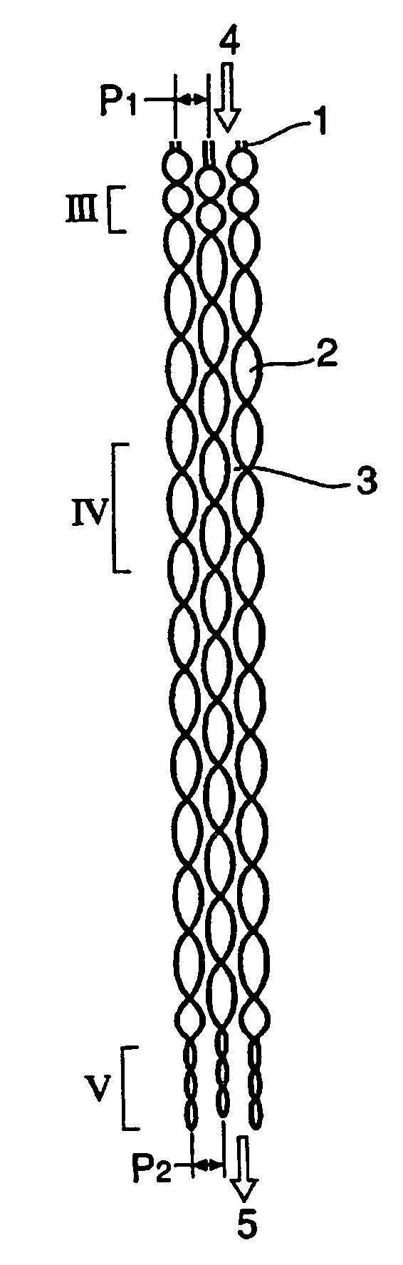
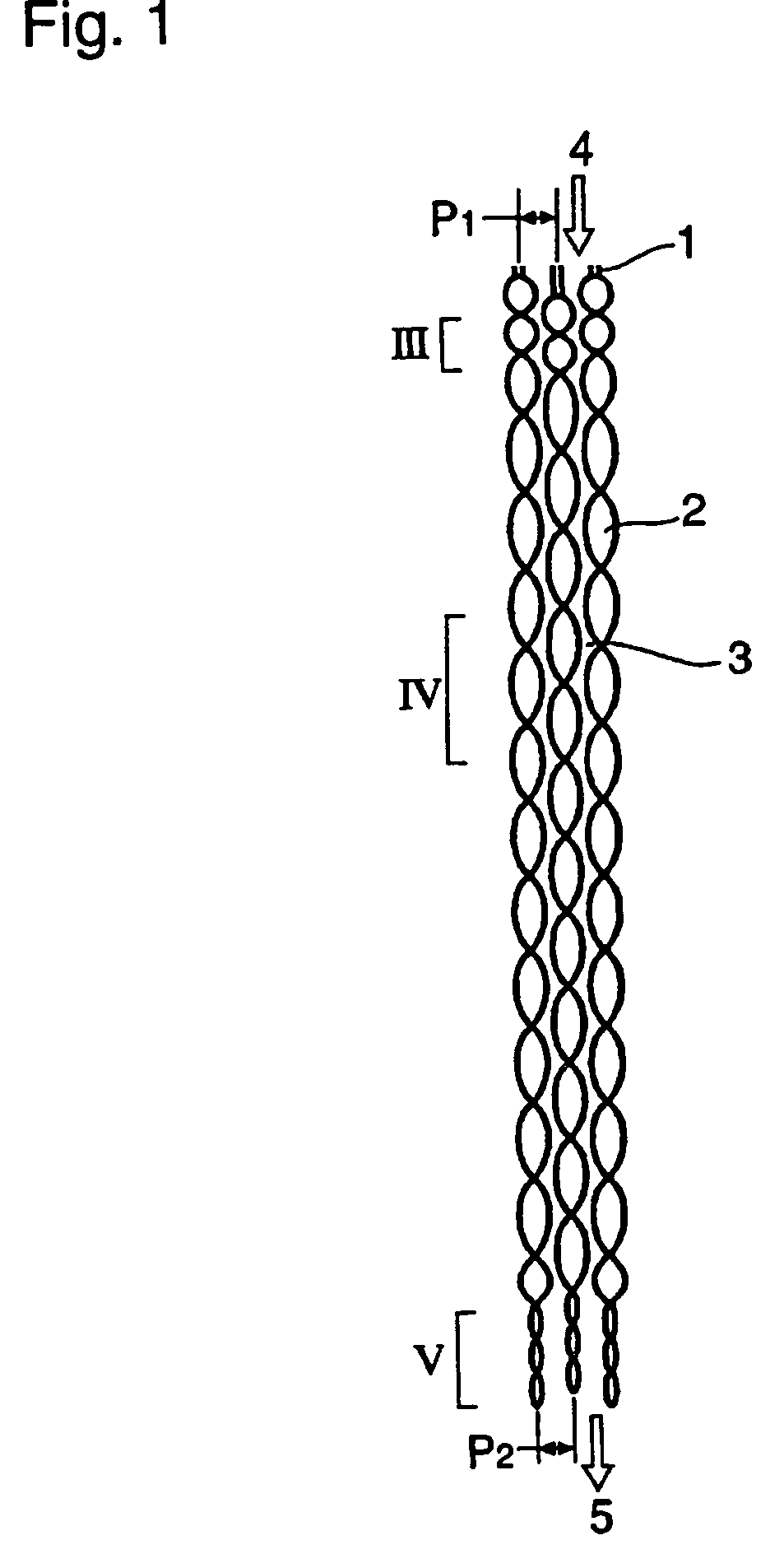
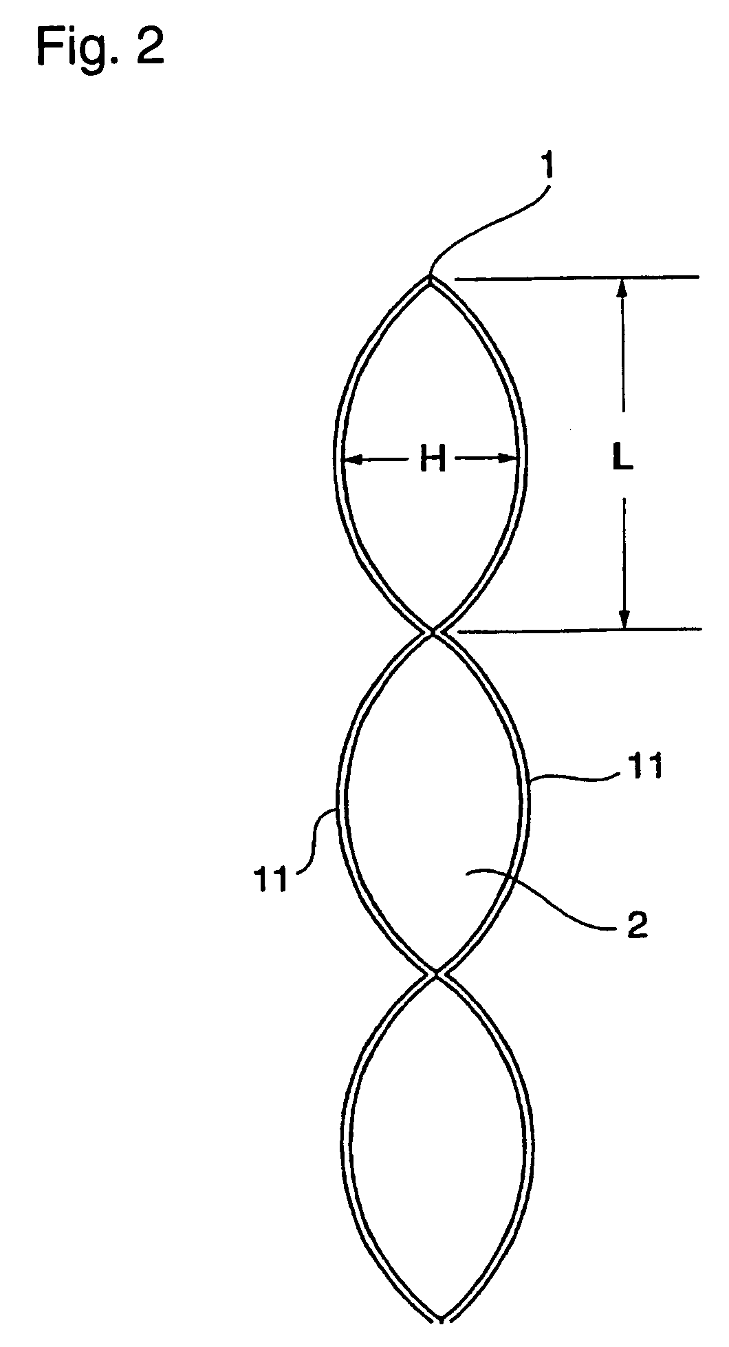
[0108]Two sets of pairs of corrugated heat transfer plates 1 were prepared. Particulars in the shape of these corrugated plates and amounts of the catalysts and an inert are shown in Table 1 described below.

[0109]

TABLE 1Shape of corrugated plateEquivalentPeriod ofHeight ofAmount filledthickness ofcor...


PUM

PropertyMeasurementUnit
lengthaaaaaaaaaa
inner diameteraaaaaaaaaa

Abstract

A plate type catalytic reactor in which components of a starting material gas react comprises a plurality of pairs of heat transfer plates, each pair being formed of two sheets of corrugated plates joined to each other and each pair having a plurality of interior heat transfer medium flow passages, that are arranged so that projected surface parts and recessed surface parts of the corrugated plates of adjacent heat transfer plates are opposed to each other and so that the plurality of pairs of corrugated plates placed in contiguous non-contacting relationship define a plurality of catalyst bed regions in which catalyst material is placed, each having an inlet for the flow of starting gas material and an outlet for the egress of reaction product, wherein the direction of flow of the heat transfer medium through the passages is perpendicular to the direction of flow of starting material gas through the plurality of catalyst regions.

Description

TECHNICAL FIELD[0001]The present invention relates to a plate type catalytic reactor for producing a useful component by transforming a gaseous starting material in a gas phase reaction accompanying heat generation or heat absorption, by using a heterogeneous solid catalyst of pellet or spherical shape. In particular, it relates to a plate type catalytic reactor capable of improving reaction performance and extending the service life of a catalyst wherein the reaction heat generated or absorbed in a catalyst layer having a heterogeneous solid catalyst is removed or supplied for heating by means of a heat transfer medium in the inner space isolated by a heat transfer plate whereby a temperature profile in the catalyst layer can effectively be controlled.BACKGROUND ART[0002]For the heterogeneous catalytic reaction using a solid catalyst of pellet or spherical shape, a fixed bed reactor or a multi-tube type reactor functioning as a heat exchanger is generally used. The multi-tube type ...

Claims


Application Information

Patent Timeline
Patent Type & Authority Patents(United States)
IPC IPC(8): B01J8/02B01J19/00B01D53/34F28F3/00B01J10/00F28F3/14B01J35/02F28F9/02B01J19/24C07B61/00C07C27/14C07C45/35C07C47/22C07C51/00C07C51/25C07C57/05F28D9/00
CPCB01J19/249C07C45/35C07C51/00F28D9/0031C07C47/22B01J2219/2453B01J2219/2455B01J2219/2459B01J2219/2462B01J2219/2481B01J8/02C07B61/00C07C27/14
Inventor SAKAKURA, YASUYUKIKAWATANI, YOUJISAITOU, TERUO
Owner MITSUBISHI CHEM CORP
Why Eureka
Try Eureka