Systems and vessels for producing hydrocarbons and/or water, and methods for same

a technology of hydrocarbons and hydrocarbon water, applied in sustainable manufacturing/processing, renewable energy generation, greenhouse gas reduction, etc., can solve the problems of troublesome, ongoing erosion of energy generating capacity, and requiring the generation of additional energy using other more costly means, and achieve the effect of lowering the current cost of using turbines

Inactive Publication Date: 2010-07-06
RUDOLPH BEHRENS +1
View PDF2 Cites 18 Cited by
  • Summary
  • Abstract
  • Description
  • Claims
  • Application Information

AI Technical Summary

Benefits of technology

[0010]It is another object to provide a clean burning fuel that is economical enough for power companies to generate a profit, by lowering the current costs for using turbines to generate electricity at levels above the base load energy level.

Problems solved by technology

There is an ongoing erosion of energy generating capacity in North America, especially with respect to base load generating facilities.
Because of environmental and industry regulation and significant market changes, utilities foresee that base load energy production will not keep pace with demand, therefore requiring the generation of additional energy using other more costly means.
This is especially troublesome because base-load energy plants are usually the most costly and time consuming to construct, traditionally being coal, nuclear, heavy oil or hydro-electric plants.
Some new combined cycle plants have slightly shorter construction time, but they are still costly to build and are dependant on natural gas or light oil, both fuels with a volatile price history.
Presently this is not possible because these turbines are simple-cycle gas turbines with a maximum thermal-dynamic efficiency of 25 percent.
Additionally, they can only be run for a limited number of hours a day since they do not conform to air pollution standards.
Use of the ocean water as the source water for potable water has been prohibitive due to the costs of treatment.

Method used


Image

  • Systems and vessels for producing hydrocarbons and/or water, and methods for same
  • Systems and vessels for producing hydrocarbons and/or water, and methods for same
  • Systems and vessels for producing hydrocarbons and/or water, and methods for same

Examples


Embodiment Construction

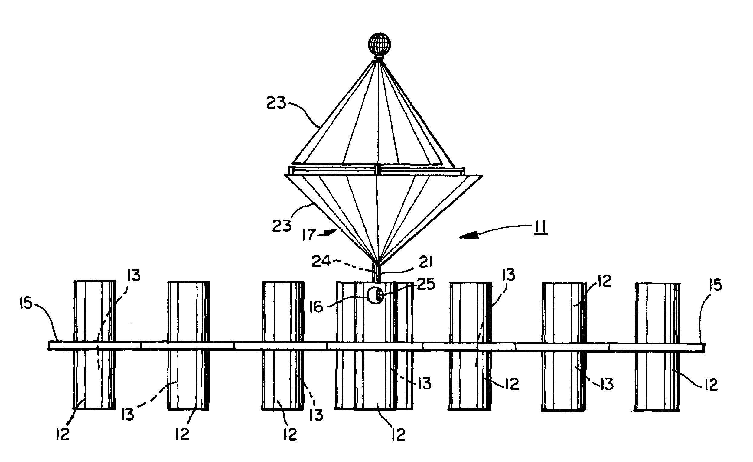
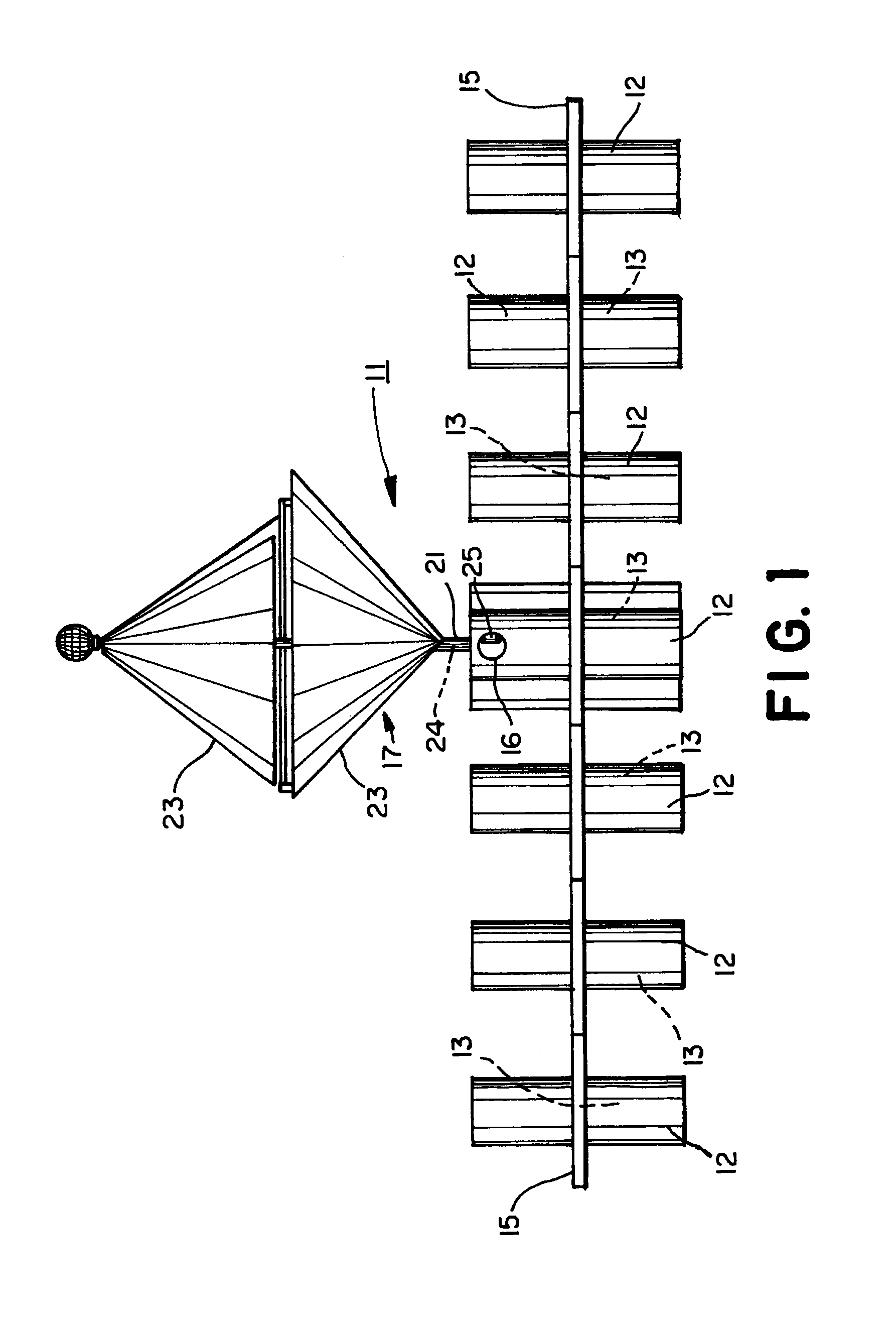
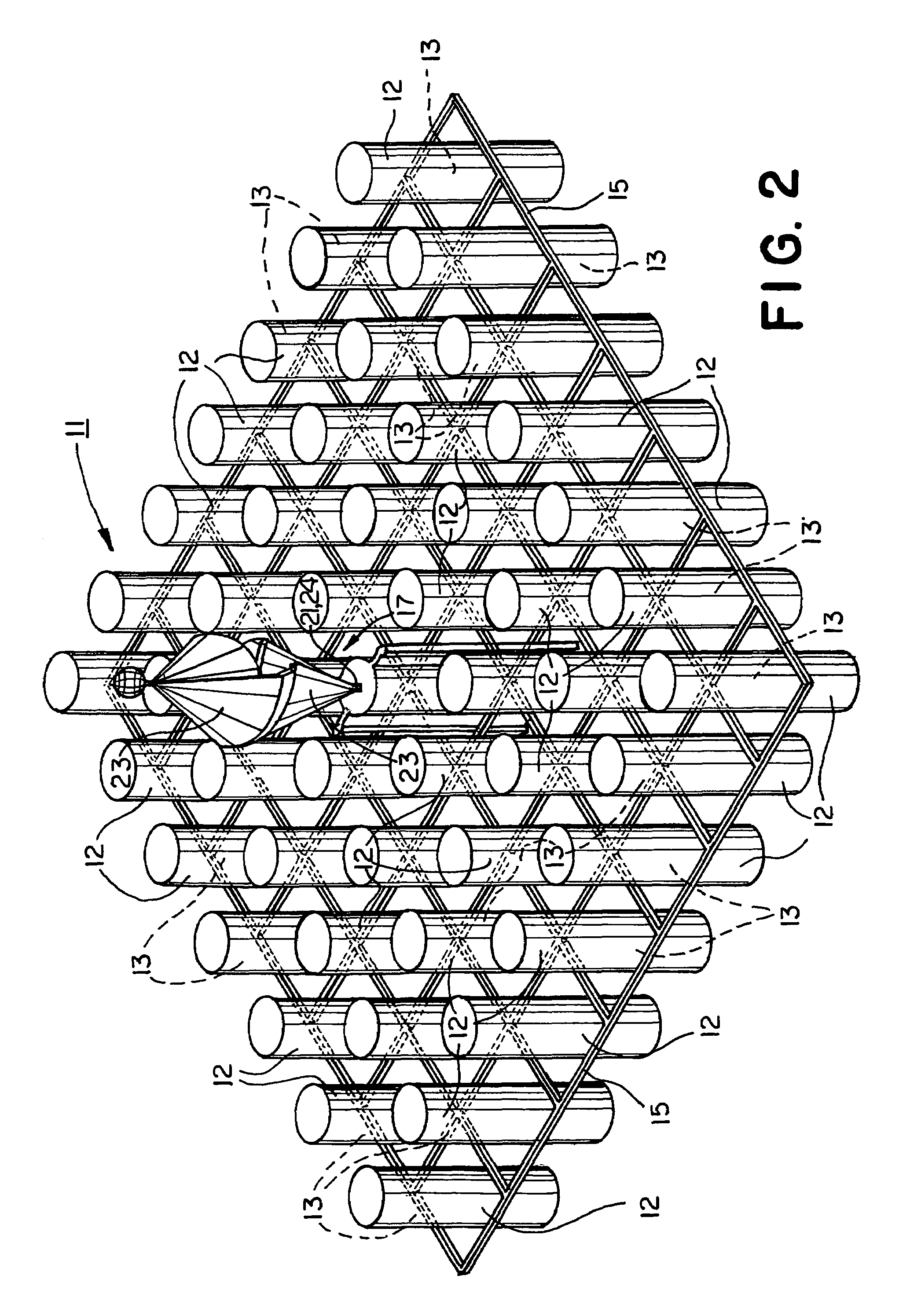
[0030]Turning to the drawings, there is shown a floating vessel 11 for producing hydrocarbons comprising one or more containers 12 having a chamber 13 formed therein, a structural frame 15 for interconnecting the one or more containers 12, a power system 16 for producing, storing, and distributing power, and a hydrocarbon processor 27.

[0031]In the preferred embodiment shown in the drawings, the structural frame 15, using structural cables 20; as shown in FIG. 4, has a tensigrity structure using a third magnitude octal truss 16 made of aluminum and stainless steel.

[0032]In this preferred embodiment, as shown in FIG. 3, vessel 11 has 81 separate containers 12 in a 9×9 array. The chambers 13 of the containers 12 serve, variously, as floatation chambers 51 (also marked with the letter “F” in FIG. 3), ballast chambers 53 (also marked with the letter “B” in FIG. 3), process chambers 55 (also marked with the letter “P” in FIG. 3), and storage chambers 57 (also marked with the letter “S” in...


PUM


Abstract

Systems and methods for producing hydrocarbons from wind energy, water, and air comprising a power system, wind turbine, and electrical generator; the system further comprises a water purifier comprising a conduit and vacuum device for flash distillation; the system further includes a hydrocarbon processor, which comprises a carbon dioxide interface, and electrolyzer, a reverse water gas shift reactor, and an ethanation reactor; alternatively the hydrocarbon processor may include a cyanobacteria cultivator a solution optimizer and a catalyzer; also included is a method for producing purified water using vegetation in a floatable craft; also disclosed is a synthetic fuel process consisting of a translucent closed tank for producing algae and a protein separator for dewatering algae; methods relating to production and drawing of algae to produce methane and other hydrocarbon promoters; also disclosed is a energy producing rainkine-cycle engine device for storing concentrated solar energy.

Description

CROSS REFERENCE TO RELATED APPLICATIONS[0001]This application claims the benefit under 35 U.S.C. Section 119(e) of prior filed provisional application No. 60 / 874,504 filed on Dec. 13, 2006; and this application claims the benefit under 35 U.S.C. Section 120 of prior filed non-provisional application Ser. No. 11 / 189,430 filed on Jul. 25, 2005, which issued as U.S. Pat. No. 7,302,903 on Dec. 4, 2007, and which claims the benefit under 35 USC Section 119(e) of prior filed provisional application No. 60 / 590,731 filed Jul. 23, 2004.BACKGROUND OF INVENTION[0002]1. Field of the Invention[0003]The present invention relates to the production of hydrocarbons and / or purified water, and more particularly concerns the production of hydrocarbons and / or purified water using air, water and wind energy as raw materials. This invention also relates to producing water utilizing trees and plantlife.[0004]2. Brief Description of Prior Art[0005]There is an ongoing erosion of energy generating capacity in...

Claims


Application Information

Patent Timeline
Patent Type & Authority Patents(United States)
IPC IPC(8): F03D9/00
CPCF03D3/005F03D9/00C25B15/08C25B1/04F05B2220/61F05B2220/62F05B2240/95Y02E10/74Y02E70/10Y02E60/366F03D9/11F03D9/25F03D9/28F03D15/10Y02E10/727Y02E60/16Y02E60/36Y02E70/30Y02P20/00Y02P20/133Y02P70/50Y02A20/141
Inventor BEHRENS, RUDOLPHBEHRENS, TODDBEHRENS, COURTNEYBEHRENS, DEREK
Owner RUDOLPH BEHRENS
Why Eureka
Try Eureka