Multicolor display apparatus

a multi-color display and display image technology, applied in the direction of discharge tube luminescent screens, discharge tube/lamp details, luminescent compositions, etc., can solve the problems of reducing productivity, reducing production costs, and reducing productivity, so as to suppress the color shift of the display image and low power consumption

Active Publication Date: 2010-07-06
CANON KK
View PDF3 Cites 9 Cited by
  • Summary
  • Abstract
  • Description
  • Claims
  • Application Information

AI Technical Summary

Benefits of technology

[0010]The present invention has been accomplished in view of the above-mentioned problems and provides a display apparatus which does not use an optical filter such as a color filter in combination, has low power consumption, and suppresses the color shift of a display image depending on a viewing angle.
[0012]According to the present invention, there can be provided a display apparatus which does not use an optical filter such as a color filter in combination, shows less color shift of a display image due to viewing angle change, has good viewing angle display quality, and has low power consumption.

Problems solved by technology

In an organic light-emitting device which constitutes a display apparatus, emitted light is reflected due to various refractive index differences, so that optical interference occurs.
Therefore, when a display apparatus is viewed from an oblique direction, the tints of the respective devices change, with the result that the white balance is lost.
However, the technique requires a step of forming the color filter.
Accordingly, there is posed the problem such that the constitution of the display apparatus becomes complicated, which reduces the productivity and increases the production cost.
In addition, there is also posed the problem that when the color filter is used, only a part of light emitted from a light-emitting layer can be extracted to the outside, which results in a reduction of the light extraction efficiency.
The technique disclosed in Japanese Patent Application Laid-Open No. 2002-367770 described above can suppress a white color shift depending on a viewing angle, but involves a problem in a trade-off relationship with the suppression effect, that the emission efficiency lowers as compared to that in the case where the peak wavelengths are caused to coincide with each other.
In particular, when the emission efficiency of a device which shows an emission color with a relatively low luminous efficiency lowers, a larger amount of energy must be input in order that desired luminance may be obtained, so that a problem such as an increase in power consumption of the display apparatus occurs.

Method used


Image

  • Multicolor display apparatus
  • Multicolor display apparatus
  • Multicolor display apparatus

Examples


example 1

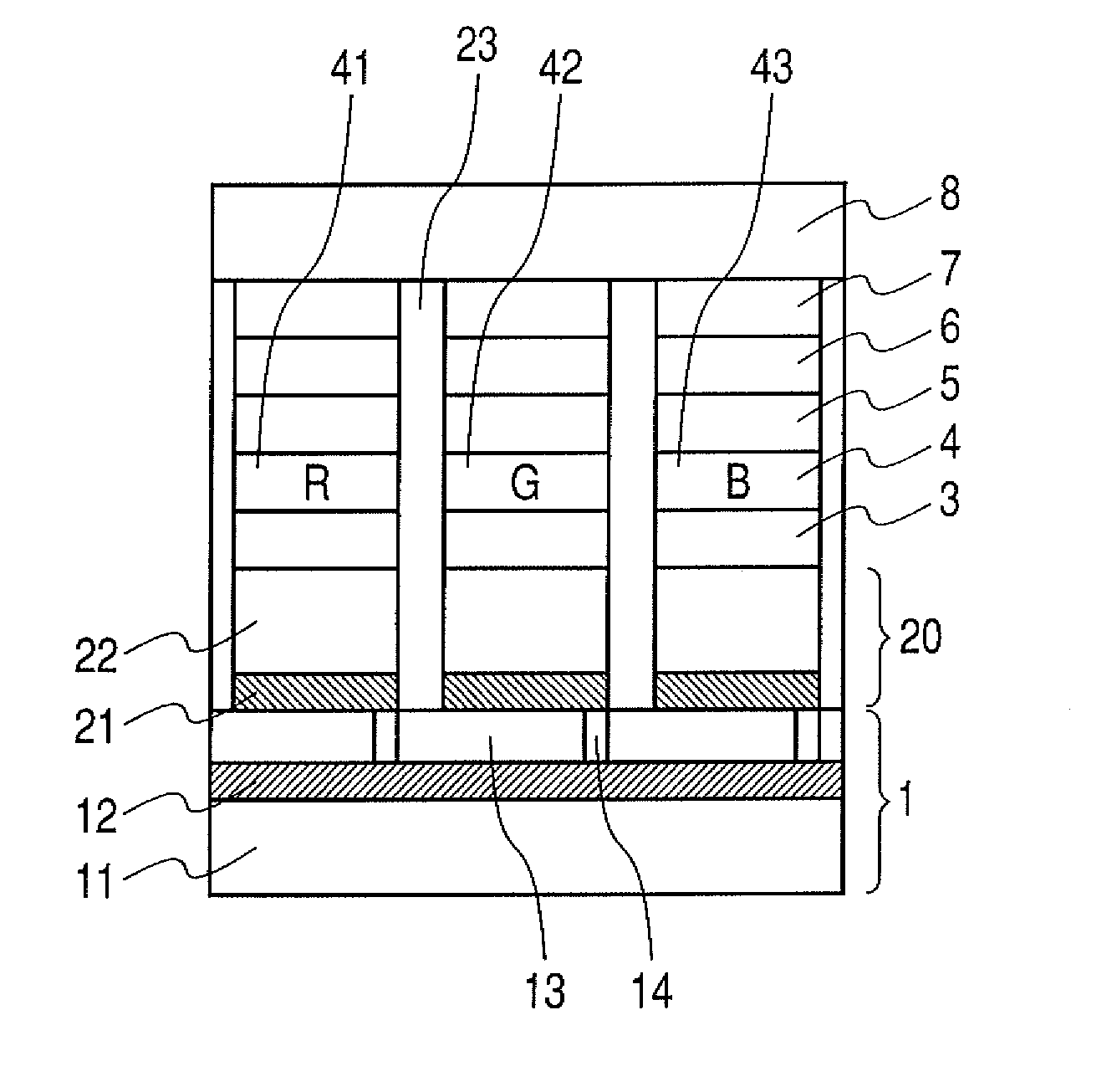
[0075]A display apparatus having a structure shown in FIG. 8 and composed of three colors, that is, a red color, a green color, and a blue color, was produced by the following method.

[0076]A TFT drive circuit 12 composed of low temperature polysilicon was formed on a glass substrate 11 as a support member, and a leveling layer 13 composed of an acrylic resin was formed thereon to prepare a substrate 1. On the substrate, a film of silver alloy (AgCuNd) was formed in a thickness of about 100 nm by sputtering, followed by patterning, thereby preparing a reflective layer 21. Further, a film of IZO was formed in a thickness of 10 nm by sputtering, followed by patterning, thereby preparing a transparent conductive film 22. Thus, the reflecting electrode 20 was formed. Further, a device isolation film 23 was formed of an acrylic resin, whereby the substrate with the anode was prepared. The substrate with anode was ultrasonically cleaned with isopropyl alcohol (IPA) and was then washed with...


PUM


Abstract

Provided is a multicolor display apparatus including a plurality of organic light-emitting devices each including a pair of electrodes of an anode and a cathode; and an organic compound layer interposed between the pair of electrodes and including a light-emitting layer. The viewing angle characteristics of the organic light-emitting device showing an emission color with a highest visual sensitivity is such that a peak wavelength of emission spectrum and a peak wavelength of multiple interference spectrum due to the organic light-emitting device are offset with respect to each other so that the color shift of a display image on the multicolor display apparatus depending on a viewing angle is suppressed.

Description

BACKGROUND OF THE INVENTION[0001]1. Field of the Invention[0002]The present invention relates to a multicolor display apparatus (hereinafter, simply referred to as “display apparatus”) including a plurality of organic light-emitting devices (organic electroluminescent devices (hereinafter, sometimes simply referred to as “device”)) each having a pair of electrodes including an anode and a cathode, and a plurality of organic compound layers interposed between the pair of electrodes and including a light-emitting layer.[0003]2. Description of the Related Art[0004]At present, display apparatuses have been vigorously researched and developed. In an organic light-emitting device which constitutes a display apparatus, emitted light is reflected due to various refractive index differences, so that optical interference occurs. The optical interference length in the device will change depending on an angle at which the device is viewed, and the emission spectrum shifts toward shorter wavelen...

Claims


Application Information

Patent Timeline
Patent Type & Authority Patents(United States)
IPC IPC(8): H01J1/62
CPCC09K11/06H01L27/3211H01L51/5265H05B33/14C09K2211/1011C09K2211/1037C09K2211/1088H01L51/0052H01L51/0053H01L51/0054H01L51/006H01L51/0067H01L51/0081H10K59/35H10K85/621H10K85/622H10K85/633H10K85/615H10K85/654H10K85/324H10K50/852
Inventor HASEGAWA, TOSHINORI
Owner CANON KK
Why Eureka
Try Eureka