
Open-path/free-space optical communication system and method using reflected or backscattered light

a technology of optical communication system and free space, applied in electromagnetic transmission, electromagnetic transmission, semiconductor lasers, etc., can solve the problem of inability to achieve optical communication between devices

Inactive Publication Date: 2010-07-06
UNIV OF SOUTH FLORIDA
View PDF17 Cites 24 Cited by
  • Summary
  • Abstract
  • Description
  • Claims
  • Application Information

AI Technical Summary

Benefits of technology

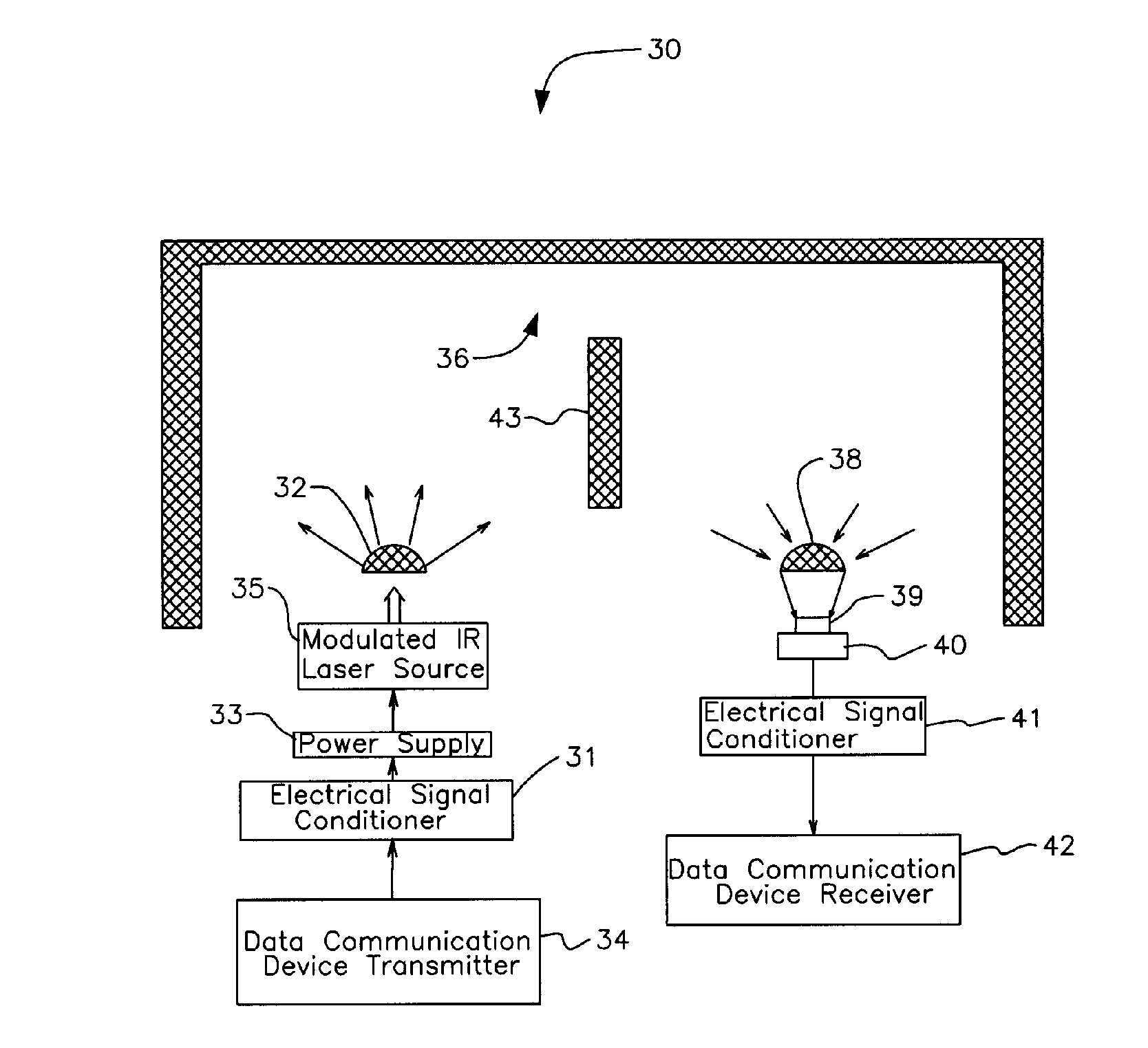
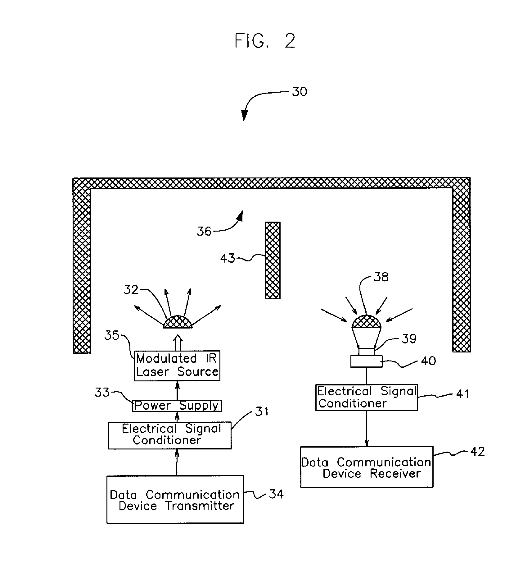
[0013]In another embodiment, the device again includes a first data communication device adapted to transmit data and a laser source modulated by the first data communication device. A first optical lens means having a π to 2π steradians field of view is positioned in light dispersing relation to the laser source. A second data communication device is adapted to receive data and an optical detector adapted to generate electrical signals corresponding to detected optical signals is connected in driving relation to the second data communication device. A second optical lens means having a π to 2π steradians field of view is positioned in light focusing relation to the optical detector. A barrier means preventing line-of-sight communication between the first and second data communication devices is adapted to be positioned in an enclosure between the first and second data communication devices.
[0020]Another embodiment includes a LIDAR communication system. More particularly, a laser is adapted to generate a LIDAR beam and a transmitting device is provided for modulating the laser. A transmit telescope is adapted to aim the LIDAR beam at a remote target and a receiver telescope is adapted to collect the LIDAR beam after the LIDAR beam has reflected or backscattered from the remote target. An optical detector means adapted to generate electrical signals upon receiving reflected light from the remote target is in light-receiving communication with the receiver telescope. A data-receiving device is adapted to receive electrical signals from the optical detector. In this way, the data-receiving device receives data from the data-transmitting device even when the data-receiving device is positioned in a location distant from the data-transmitting device even when at least one obstacle prevents line-of-sight communication between the data-transmitting device and the data receiving device.
[0023]It is a further object of the invention to provide an open-path laser beam communication system that can convey information between two or more buildings even when one or more physical objects are positioned in a line-of-sight path between said buildings.

Problems solved by technology

When a clear line of sight between the source and destination does not exist, optical communication between the devices has not been feasible because physical objects positioned in the line-of-sight path easily block direct line-of-sight communication.

Method used


Image

  • Open-path/free-space optical communication system and method using reflected or backscattered light
  • Open-path/free-space optical communication system and method using reflected or backscattered light
  • Open-path/free-space optical communication system and method using reflected or backscattered light

Examples


Embodiment Construction

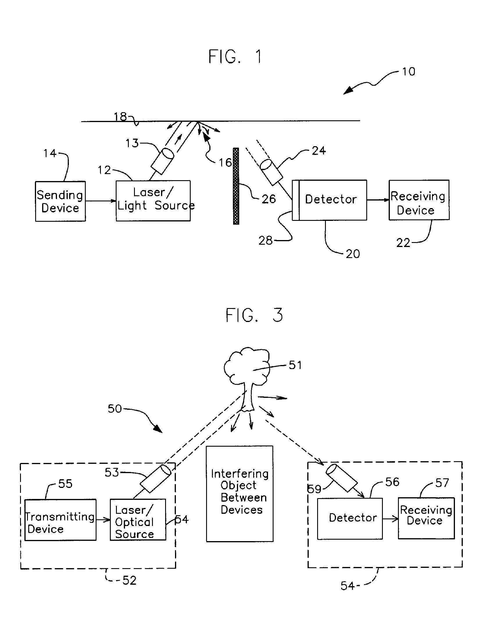
[0028]Referring now to FIG. 1, it will there be seen that an illustrative embodiment of the novel laser communication system is denoted as a whole by the reference numeral 10. It should first be observed in said FIG. 1 that a laser beam following a path of travel between the light source and the detector is constrained to follow a generally “V”-shaped path of travel because said laser light source and said detector are positioned out of line-of-sight relation to one another because there is a barrier between them. The same initial observation should be made in connection with FIGS. 2-4 as well.

[0029]System 10 includes laser generator or other light source 12 connected in communication modulation relation to sending device 14, i.e., sending device 14 modulates laser generator 12. Laser source 12 is adapted to generate light at multiple wavelengths simultaneously. Transmitter telescope 13 is adapted to aim a laser or other optical beam from laser generator 12 toward a target area 16 w...


PUM


Abstract

An open-path / free-space optical communication system using reflected light has modulated optical or laser sources and provides communication between the modulated source and a detector in an obstructed line-of-sight relationship. The system detects backscattered light impinging on a target illuminated by the source of light. Barrier objects positioned in a line-of-sight path between the source and detector are circumvented and a first device that provides the modulation signal for the source controls a remote second device.

Description

RELATED APPLICATIONS[0001]The present application is a continuation of prior filed International Application No. PCT / US02 / 02866, filed Jan. 30, 2002, which claims the benefit of U.S. Provisional Application No. 60 / 265,022, filed Jan 30, 2001.BACKGROUND OF THE INVENTION[0002]1. Field of the Invention[0003]This invention relates to systems and methods for relaying information between two or more points by using laser or optically generated conductive transport means through the atmosphere to convey the information.[0004]2. Description of the Prior Art[0005]Open-path, or free space optics, is a line-of-sight technology that enables optical transmission of data, voice and video communications through the air, thereby providing optical connectivity without the need for expensive fiber-optic cable.[0006]Free-Space optical systems can operate over a distance of several kilometers, provided the transmitting laser and the receiver are in a direct line-of-sight relationship. When a clear line...

Claims


Application Information

Patent Timeline
Patent Type & Authority Patents(United States)
IPC IPC(8): H04B10/00H01S3/139H01S5/0687H04B10/10H04B10/155
CPCH04B10/11H04B10/1121H04B10/1141H04B10/506H01S3/1392H01S5/0687
Inventor KILLINGER, DENNIS K.
Owner UNIV OF SOUTH FLORIDA
Learn More