
Hydrogen resistant optical fiber formation technique

a technology of optical fiber and hydrogen, which is applied in the direction of glass production, glass making apparatus, manufacturing tools, etc., can solve the problems of reducing the transmission quality of optical fiber, oxidizing agent, and fibers are more susceptible to hydrogen-induced loss

Active Publication Date: 2010-07-13
BAKER HUGHES INC
View PDF24 Cites 21 Cited by
  • Summary
  • Abstract
  • Description
  • Claims
  • Application Information

AI Technical Summary

Benefits of technology

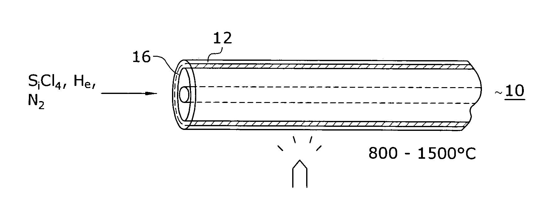
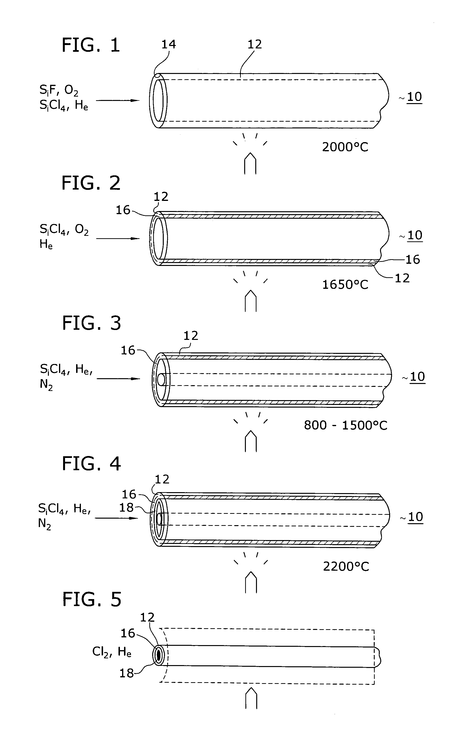
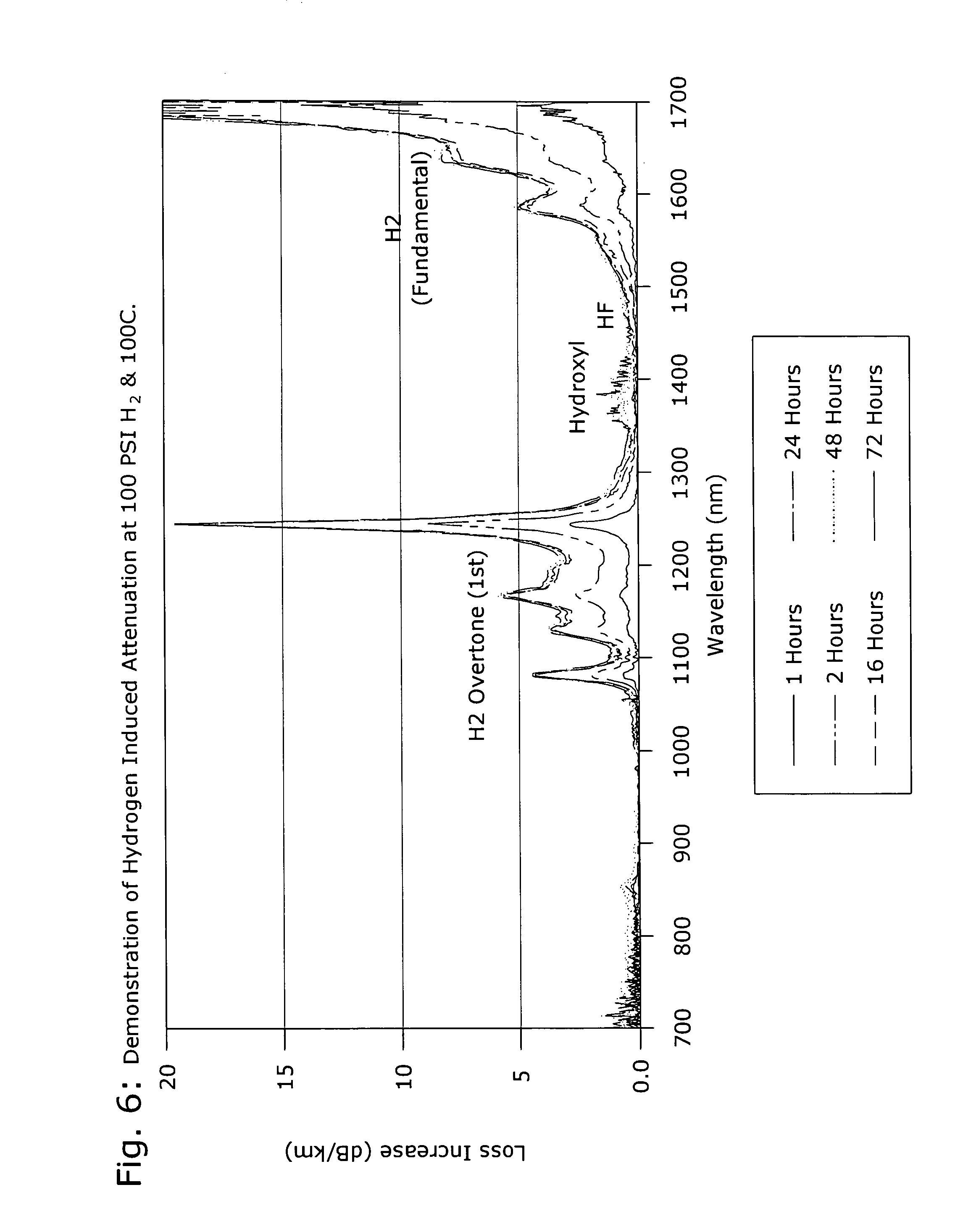
[0008]The needs remaining in the prior art are addressed by the present invention, which relates to a hydrogen resistant optical fiber formation technique and, more particularly, to the initial use of an unsintered soot, subjected to a treatment with a metal halide vapor, to eliminate the formation of Si—OH when the drawn fiber is thereafter exposed to hydrogen at various pressures and temperatures.
[0010]Advantageously, the presence of SiCl4 (without oxygen) has been found to eliminate oxygen-rich defects (Si—O—O—Si) present in the structure as a result of the soot deposition process. The separation of the soot deposition and sintering processes by the SiCl4 “scrubbing” thus significantly reducing hydrogen-induced attenuation in the final structure.

Problems solved by technology

Subsequent to formation of the fiber, hydrogen may also become incorporated in the composition and thus compromise the transmission qualities of the fiber.
A disadvantage of these various techniques is the need for an oxidizing agent, since the presence of excess oxygen in the glass makes the fiber more susceptible to hydrogen-induced loss during subsequent cabling or use in the field.

Method used


Image

  • Hydrogen resistant optical fiber formation technique
  • Hydrogen resistant optical fiber formation technique
  • Hydrogen resistant optical fiber formation technique

Examples


Embodiment Construction

[0022]The motivation for the concepts developed in accordance with the present invention is to improve the resistance of optical fiber to hydrogen-induced loss typically seen in harsh environments, such as the use of fiber optic sensors within an oil well. Such an environment cannot be well-controlled to guarantee that water or other contaminants will not be present. The silicon defects introduced into the optical fiber during a conventional prior art manufacturing process typically result in SiOH and SiH losses in the fiber, due to the reaction over time between the Si defects and hydrogen. It is thought that the oxygen-rich defects are responsible for the formation of Si—OH and the increased loss at 1385 nm. The oxygen-rich defects arise due to excess oxygen atoms present in the silica glass, resulting from preform fabrication in an environment with too much oxygen. Furthermore, the introduction of impurity dopants (for example, germanium) can generate defects that result in creas...


PUM

PropertyMeasurementUnit
Temperatureaaaaaaaaaa

Abstract

A method of forming an optical fiber preform using, for example, an MCVD process, is modified to reduce the presence of hydrogen-induced transmission losses in an optical fiber drawn from the preform. A relatively porous, unsintered soot layer is first formed (similar to the initial soot layer commonly associated with the solution-doped process of the prior art) and then subjected to a flow of a metal halide (such as SiCl4) to reduce the presence of excess oxygen. It is imperative that the metal halide treatment occur in the absence of oxygen. Sintering of the treated layer, followed by a conventional collapsing process is then used to form the inventive preform. In accordance with the present invention, both the sintering and collapsing steps are performed in a non-oxygen based ambient. When the drawn fiber is then later exposed to hydrogen, the lack of oxygen thus eliminates the formation of Si—OH and the associated attenuation problems.

Description

TECHNICAL FIELD[0001]The present invention relates to a hydrogen resistant optical fiber formation technique and, more particularly, to the initial use of an unsintered soot, subjected to a treatment with a metal halide vapor, to eliminate the formation of Si—OH when exposed to hydrogen at various pressures and temperatures.BACKGROUND OF THE INVENTION[0002]In the art of fiber preform manufacture for transmission fibers, techniques have been developed for high speed manufacture using a chemical vapor deposition process, which has been found to be relatively inexpensive, while also providing a high quality fiber. In this process, the necessary cladding and core constituents are supplied in their vapor phase to a horizontally rotated refractory tube to form one or more inner glass layers on the inside surfaces of the tube. Exemplary of this technique is U.S. Pat. No. 4,909,816, issued to MacChesney et al., and its companion patents U.S. Pat. Nos. 4,217,027 and 4,334,903, disclosing wha...

Claims


Application Information

Patent Timeline
IPC IPC(8): C03B37/018
CPCC03B37/01815C03B37/01853Y02P40/57
Inventor HOMA, DANIEL SCOTT
Owner BAKER HUGHES INC
Learn More