Image forming apparatus having energy-saving mode, control method therefor, network system including the image forming apparatus, and control method therefor
a technology of image forming apparatus and energy-saving mode, which is applied in the direction of digital output to print units, electric controllers, instruments, etc., can solve the problems of suffering of the above-described network system according to the prior art, and achieve the effect of reducing power consumption mode, less electric power, and reducing power consumption
- Summary
- Abstract
- Description
- Claims
- Application Information
AI Technical Summary
Benefits of technology
Problems solved by technology
Method used
Image
Examples
first embodiment
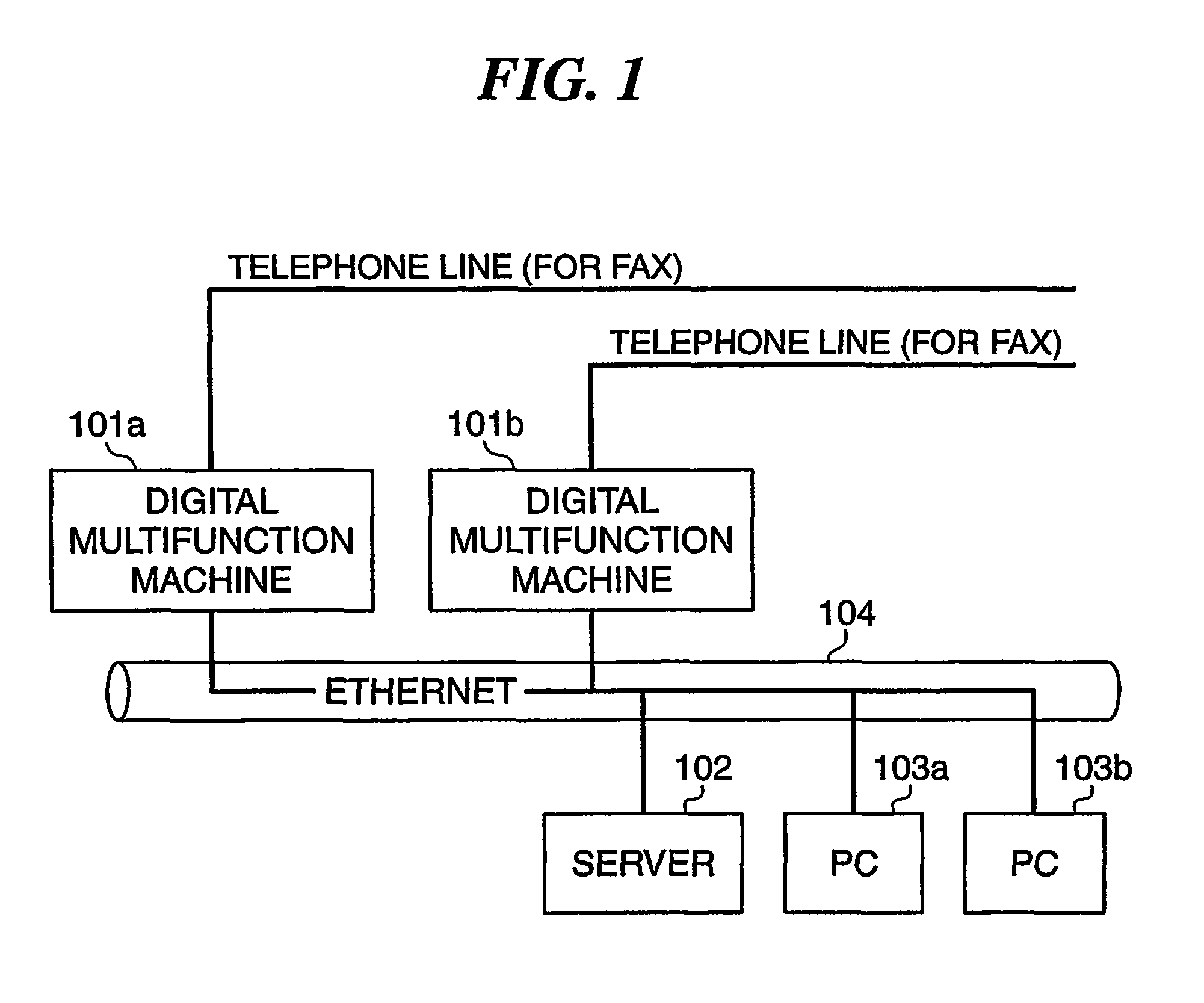
[0051]FIG. 1 is a block diagram showing an example of the configuration of a network system to which to which is applied a method of controlling a network system, according to the present invention. Needless to say, the image forming apparatuses to which is applied the method according to the present invention include printing apparatuses (printers) using the electrophotographic printing method, the ink jet printing method, and other printing methods, facsimile machines or digital multifunction machines for performing multiple function image forming processing, including print processing and facsimile processing. Hereinafter, a description will be given of digital multifunction machines by way of example.
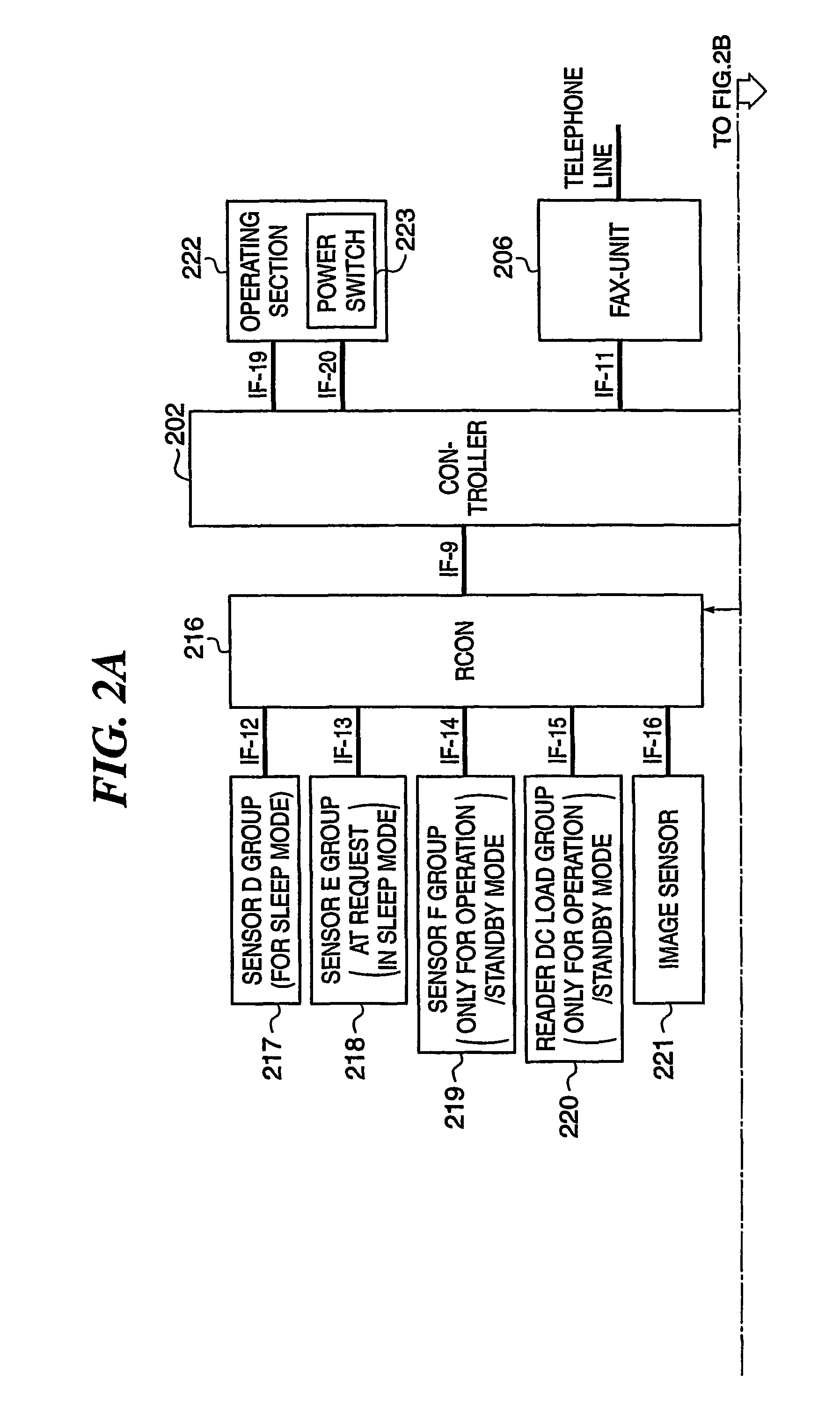
[0052]In FIG. 1, reference numerals 101a and 101b designate digital multifunction machines, each of which is operated by electric power supplied to a printer section (DCON) 201, a reader section (RCON) 216, and a controller 202 thereof, from a DC power supply 203, as described in de...
second embodiment
[0222]Next, the present invention will be described.
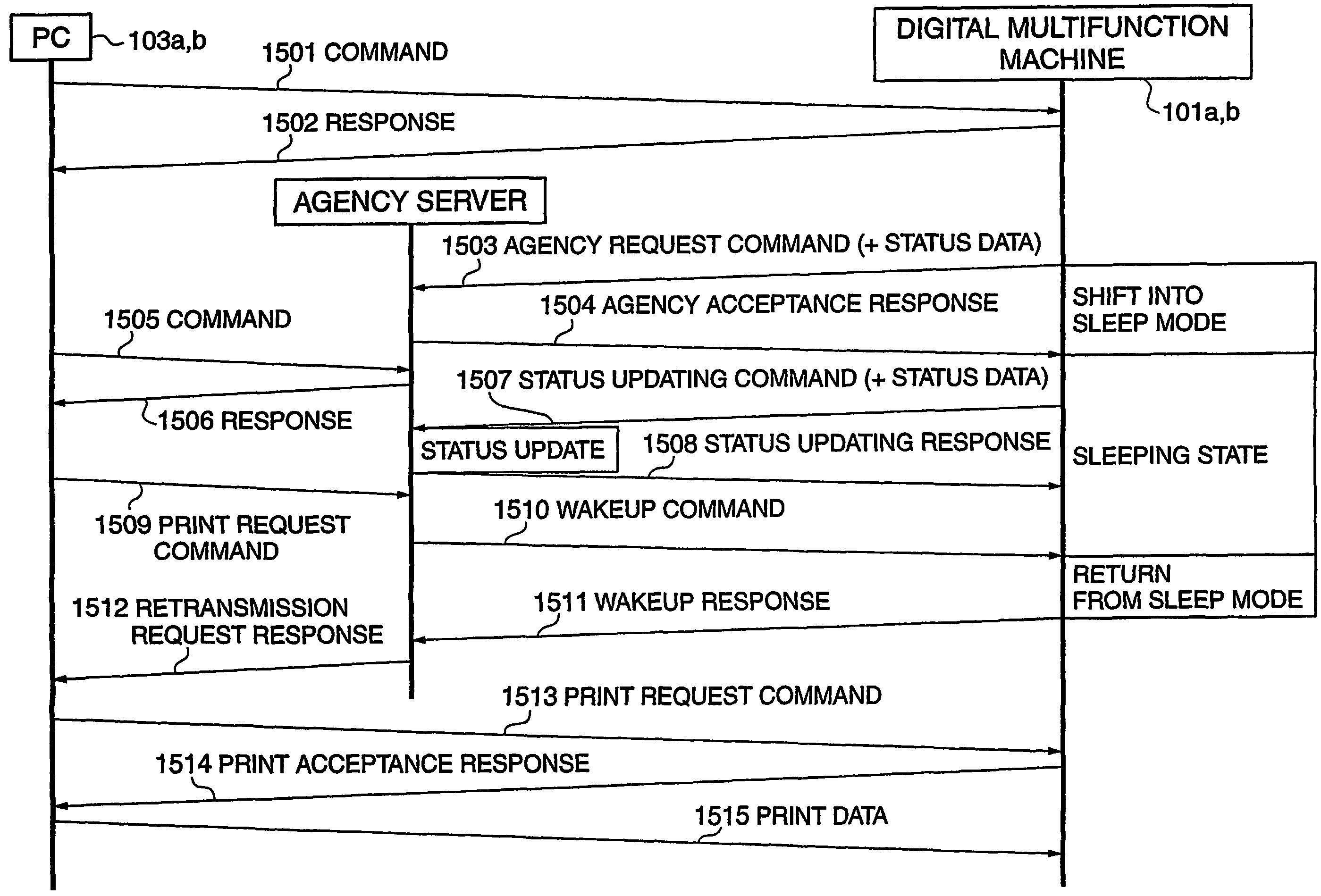
[0223]The second embodiment is distinguished from the above described first embodiment in which when the image forming apparatus (digital multifunction machine 101a (101b)) receives a status request from an external device via the network during the sleep mode, the sub CPU (1-chip microcomputer Q702) transmits status information to the external device in place of the main CPU (main-chip microcomputer Q701), in that only when there is any change in the status during the sleep mode, the sub CPU transmits status information to an agency server (server 101), and a status request received via the network by the image forming apparatus is responded to not by the sub CPU, but by the agency server 102.
[0224]FIG. 15 is a block diagram showing details of the arrangement of a controller and its related parts of an image forming apparatus to which the method according to the second embodiment of the present invention is applied. Component part...
third embodiment
[0293]Next, the present invention will be described.
[0294]Although in the above described first and second embodiments, the sub CPU (1-chip microcomputer Q702) and the main CPU (main-chip microcomputer Q701) are physically separate from each other, this is not limitative. In the present embodiment, a single chip (CPU) is operated with a high-frequency clock in the normal mode, and operated with a low-frequency clock in the energy-saving mode. Further, in the energy-saving mode, a local power supply in the single chip is saved, and the chip is driven with small power consumption.
[0295]The present invention includes a combination of the above described embodiments.
[0296]Hereafter, a description will be given of a data processing program that can be read by the image forming apparatus according to any one of the above described embodiments, by referring to a memory map shown in FIG. 23.
[0297]FIG. 23 is a diagram showing the structure of a memory map of a storage medium that stores vari...
PUM
 Abstract
Description
Claims
Application Information
 - R&D
- Intellectual Property
- Life Sciences
- Materials
- Tech Scout
- Unparalleled Data Quality
- Higher Quality Content
- 60% Fewer Hallucinations
Browse by: Latest US Patents, China's latest patents, Technical Efficacy Thesaurus, Application Domain, Technology Topic, Popular Technical Reports.
© 2025 PatSnap. All rights reserved.Legal|Privacy policy|Modern Slavery Act Transparency Statement|Sitemap|About US| Contact US: help@patsnap.com


