Apparatus on a spinning preparation machine, especially a flat card, roller card, or the like, for adjusting the carding clearance

a technology of preparation machine and carding clearance, which is applied in the direction of carding machine, textiles and papermaking, fibre treatment, etc., can solve the problems of different thermal expansion, large heat generation owing to mechanical work, and different thermal expansion, so as to avoid or mitigate the

Inactive Publication Date: 2010-07-20
TRUETZSCHLER GMBH & CO KG
View PDF15 Cites 0 Cited by
  • Summary
  • Abstract
  • Description
  • Claims
  • Application Information

AI Technical Summary

Benefits of technology

[0010]It is an aim of the invention to produce an apparatus of the kind mentioned at the beginning, which avoids or mitigates the said disadvantages, and which in particular in a simple manner allows a uniform carding gap (carding clearance), preferably under different production and processing conditions.
[0012]Because the energy, preferably heat, is generated by an external device, that is, a device that is present expressly for the purpose of inputting energy to one of the components defining the carding gap, preferably a heater apparatus, this enables an influence independent of the constant carding heat to be exerted on the contour of at least one of the components facing each other. In this simple manner the contour can be specifically altered and adjusted during operation so that the carding gap is constant across the width. A particular advantage is that even in the case of different production and processing conditions, the carding clearance is correspondingly adjustable to accommodate them. The temperature gradient is neatly minimised across the working width and the thermal expansion is thereby rendered uniform.

Problems solved by technology

With the work surface remaining constant, increasing throughput of fibre material (output) leads to greater generation of heat owing to the mechanical work.
The high-performance card concerned then suffers considerable damage.
Moreover, in particular the generation of heat in the working region of the card can lead to different thermal expansions when the temperature differences between components are too large.
A large carding gap, however, leads to undesirable nep formation in the card sliver.
With reference to the cylinder, there is a further problem in that it is unevenly heated across the working width as a result of varying material coverage and fluctuations in the gap as a consequence of manufacturing tolerances.
The different thermal expansion brought about by this causes a convexly shaped bulging (camber) of the cylinder and thus impairs the carding gap.
The carding result is consequently adversely affected.
Since the cylinder is a counterpart for all carding and separation points, this loss of quality occurs at all points.
The disadvantage is that the carding gap is thus uneven across the width of the card and in the middle region there is a risk of collision between the components.
One disadvantage is that presetting of a specific concave contour allows only a single alteration in the curved shape of the elements during operation.
Adaptation to changed processing conditions, especially a change in the fibre material volume and quality, is therefore not possible.
In addition, it is inconvenient that the inherent heat of the elements in operation, which causes the expansions, is constant, so that the curved form is correspondingly constant and cannot be adapted to changed production conditions.

Method used


Image

  • Apparatus on a spinning preparation machine, especially a flat card, roller card, or the like, for adjusting the carding clearance
  • Apparatus on a spinning preparation machine, especially a flat card, roller card, or the like, for adjusting the carding clearance
  • Apparatus on a spinning preparation machine, especially a flat card, roller card, or the like, for adjusting the carding clearance

Examples


Embodiment Construction

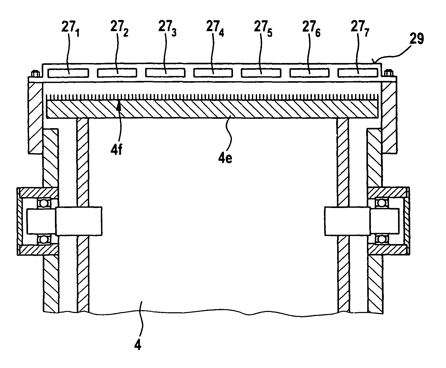
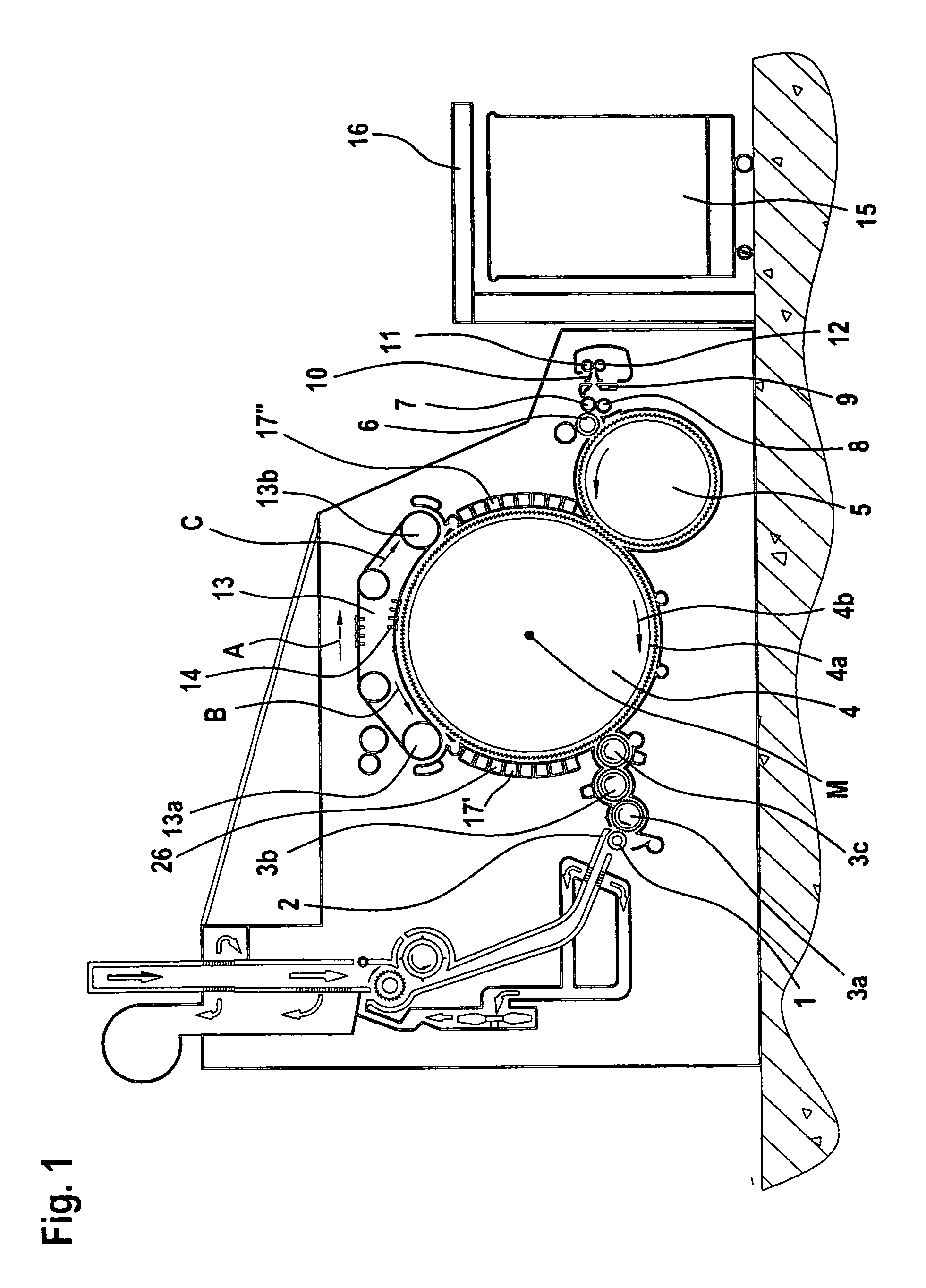
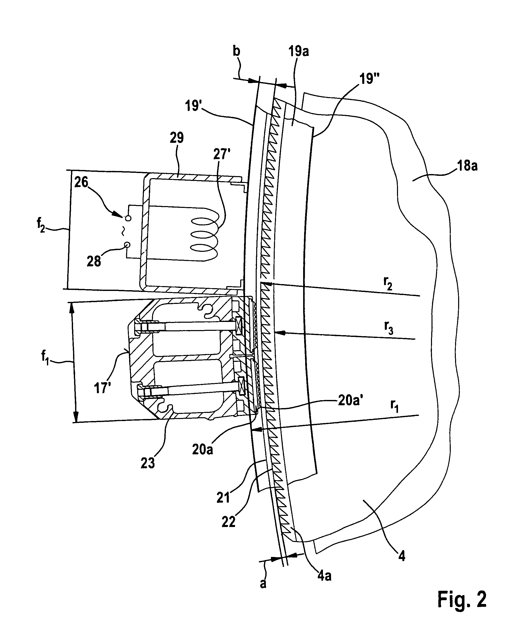
[0033]With reference to FIG. 1 a card, for example, the card TC 03 made by Trützschler GmbH & Co. KG of Monchengladbach, Germany, has a feed roller 1, feed table 2, licker-ins 3a, 3b, 3c, cylinder 4, doffer 5, stripping roller 6, squeezing rollers 7, 8, web-guide element 9, web funnel 10, take-off rollers 11, 12, revolving flat 13 with flat guide rollers 13a, 13b and flat bars 14, can 15 and can coiler 16. The directions of rotation of the rollers are shown by respective curved arrows. The letter M denotes the midpoint (axis) of the cylinder 4. The reference numeral 4a denotes the clothing and reference numeral 4b denotes the direction of rotation of the cylinder 4. The letter B denotes the direction of rotation of the revolving flat 13 in the carding position and the letter C denotes the reverse transport direction of the flat bars 14. Stationary cover and work elements, e.g. stationary carding elements 17I, are arranged between the licker-in 3c and the rear flat guide roller 13a a...


PUM

PropertyMeasurementUnit
distanceaaaaaaaaaa
circumferential speedaaaaaaaaaa
energyaaaaaaaaaa

Abstract

An apparatus is provided on a spinning preparation machine for adjusting the carding clearance. A clothed roller has a cylindrical peripheral surface and a cladding facing and spaced therefrom, wherein between the peripheral surface of the roller and a part of the cladding there is a carding region with a carding clearance where carding work is performed and carding heat is generated, heat leading to an alteration across the width of the machine in the contour of at least one of the components lying opposite each other. In order in simple manner to allow a uniform carding clearance under different production and processing conditions, the carding clearance can be made smaller by external energy input to at least one of the components facing each other and / or can be enlarged by throttling the energy input and the energy input.

Description

CROSS REFERENCE TO RELATED APPLICATION[0001]This application claims priority from German Patent Application No. 10 2006 014 419.8 dated Mar. 27, 2006, the entire disclosure of which is incorporated herein by reference.BACKGROUND OF THE INVENTION[0002]The invention relates to an apparatus on a spinning preparation machine, especially a flat card, roller card or the like, for adjusting the carding clearance.[0003]It is known for a clothed roller, for example a cylinder, to have a cylindrical peripheral surface facing and spaced radially from a cladding, wherein between the peripheral surface of the roller and a part of the cladding there is a carding region with a carding clearance between clothings facing each other where carding work is performed and carding heat is generated, and in which heat leads to an alteration across the width of the machine in the contour of at least one of the components facing each other.[0004]The distances between the cylinder clothing and surfaces (count...

Claims


Application Information

Patent Timeline
Patent Type & Authority Patents(United States)
IPC IPC(8): D01G15/12
CPCD01G15/28
Inventor SCHMITZ, THOMAS
Owner TRUETZSCHLER GMBH & CO KG
Why Eureka
Try Eureka