Electrical lighting device

a technology of electric lighting and lighting devices, applied in the direction of coupling device connections, coupling protective earth/shielding arrangements, tumbler/rocker switches, etc., can solve the problems of not being able to search a room in this manner, not being able to readily find light switches, and not being able to maximize the effective area of illumination, sacrificing sensor isolation, and high degree of illumination

Inactive Publication Date: 2010-07-20
PASS SEYMOUR
View PDF25 Cites 65 Cited by
  • Summary
  • Abstract
  • Description
  • Claims
  • Application Information

AI Technical Summary

Benefits of technology

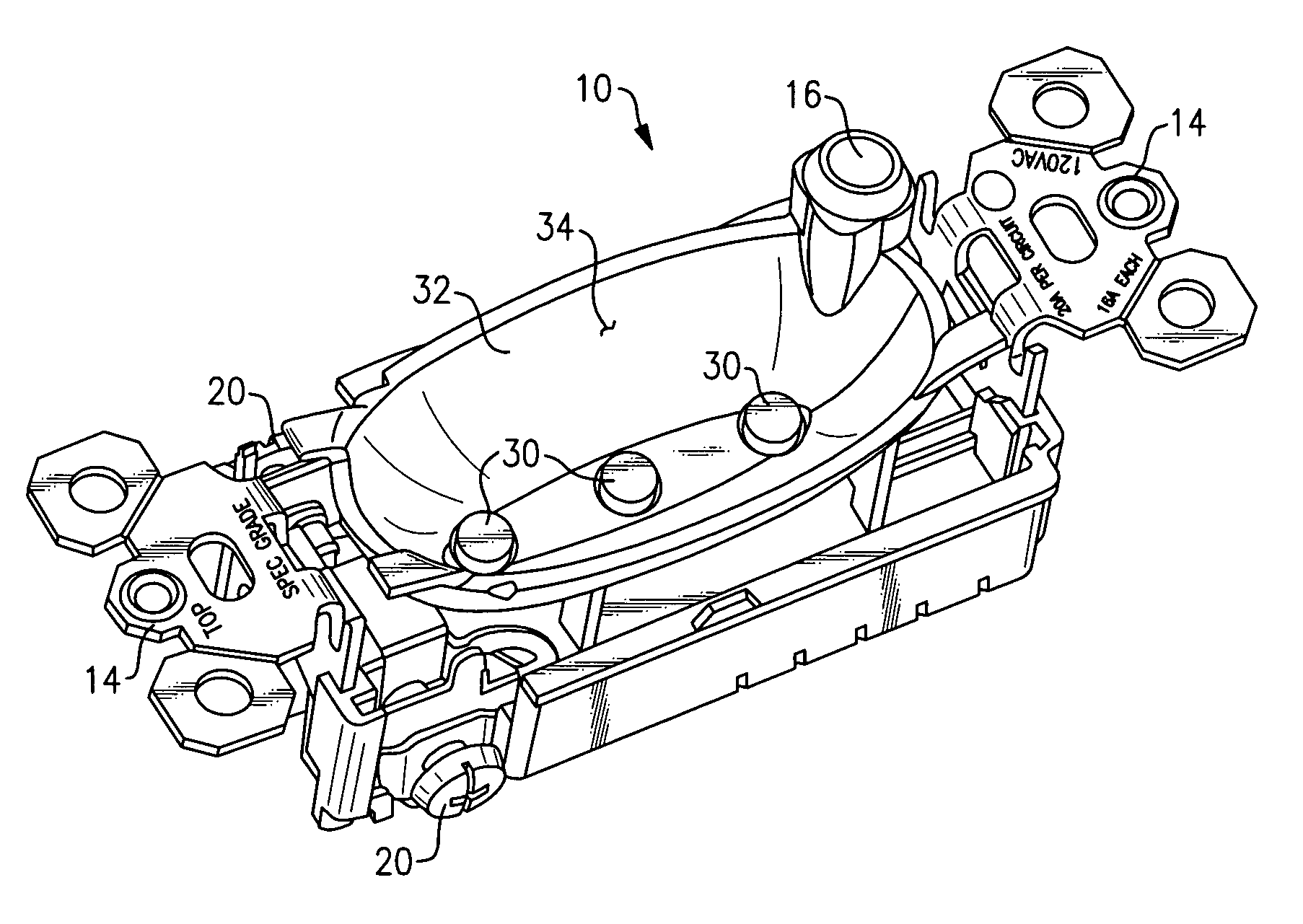
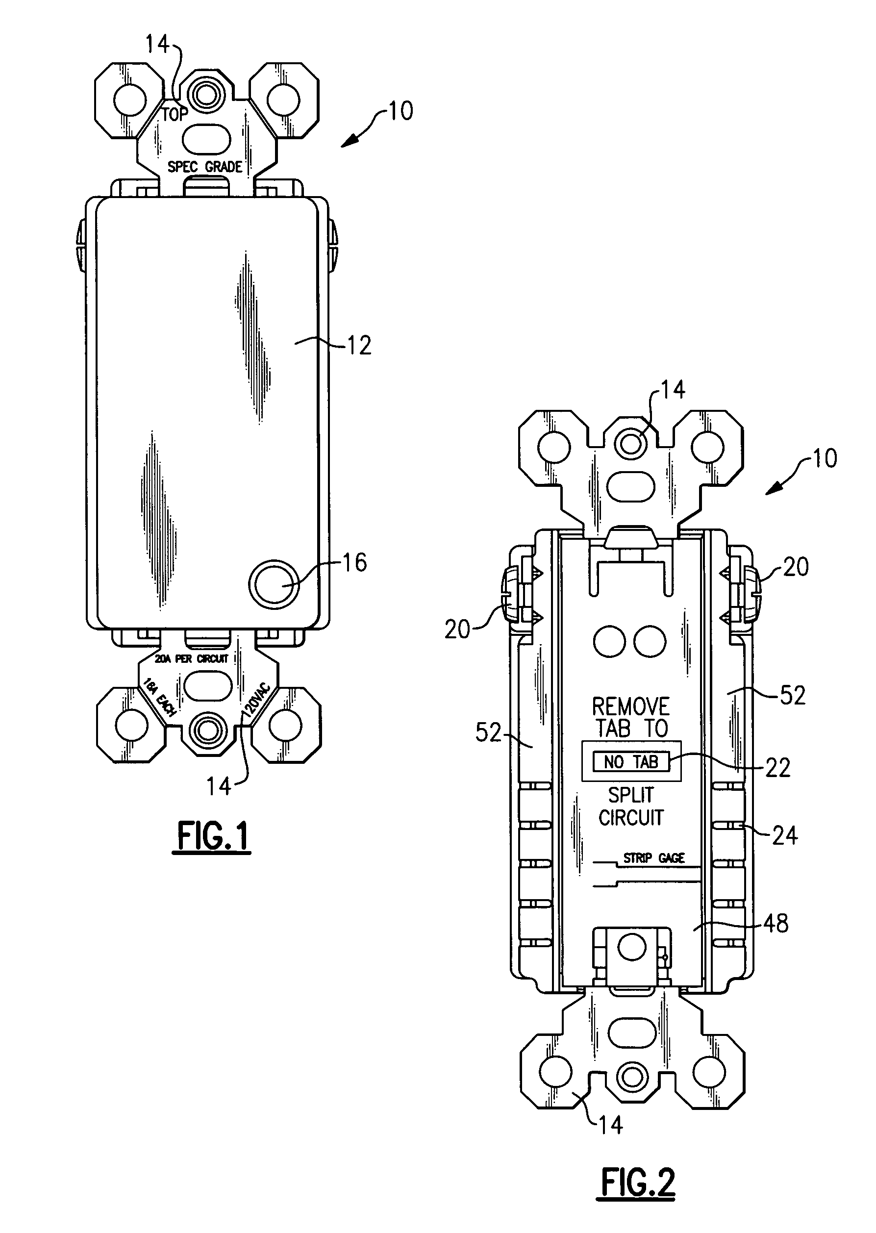
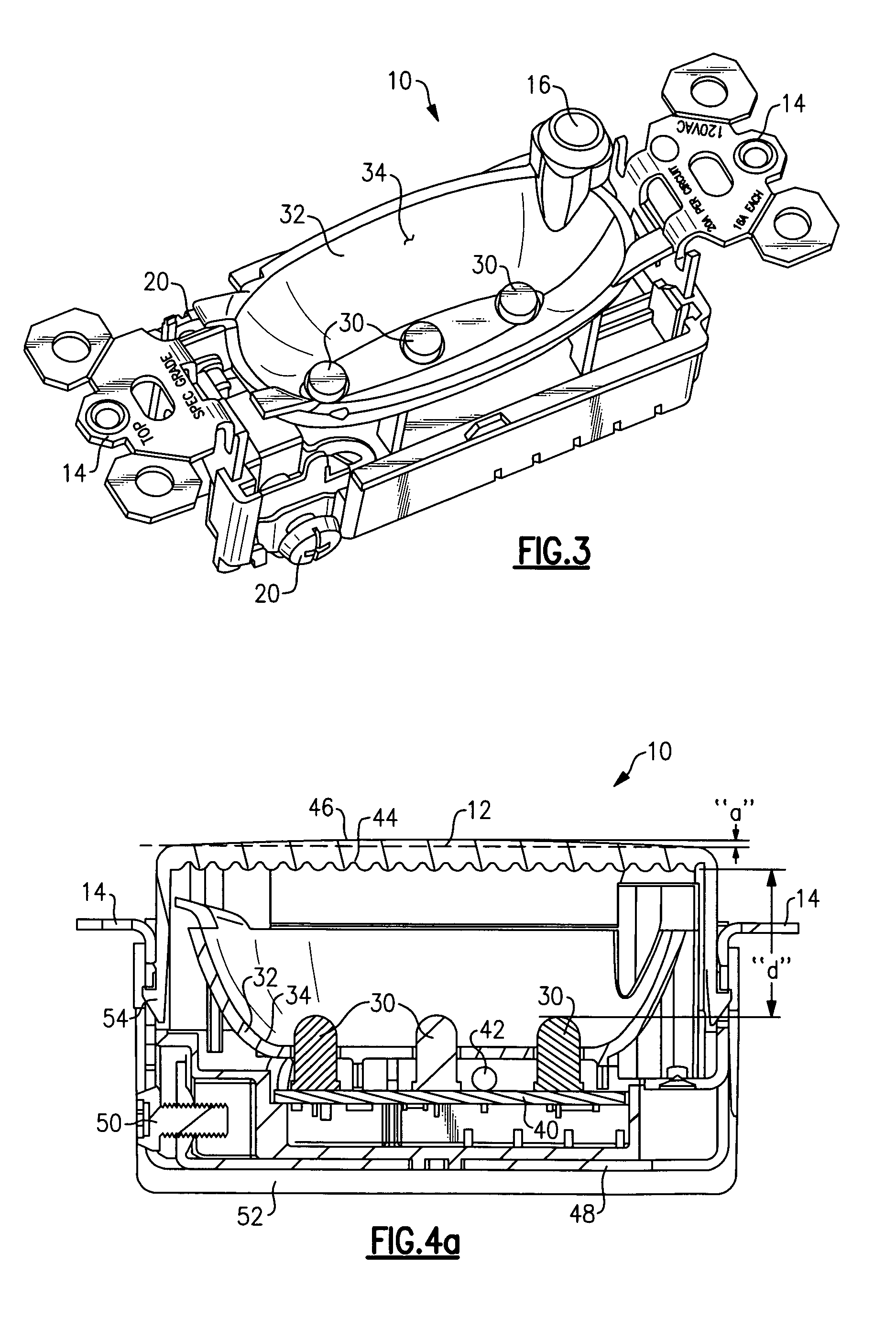
[0011]The present invention addresses the needs described above by providing a light source that is both adapted to various wiring device form factors and configured to address the drawbacks and needs described above. The light emitting wiring device of the present invention provides a high degree of illumination when the ambient light in a given space falls below a safe level by maximizing the effective area of illumination without sacrificing sensor isolation. For example...

Problems solved by technology

If an object is disposed relatively low to the floor surface the person may trip over it and suffer an injury.
Accordingly, searching a room in this manner is not recommended because of the aforementioned safety issues.
As noted above, there are situations where a light switch is not available, or is not readily available.
A person entering a darkened theatre would expect to incur the wrath of his fellow patrons if he turned the theatre lights ON while finding a seat.
While this arrangement may provide adequate illumination and temporarily mitigate a potentially unsafe condition, it has certain drawbacks associated with it.
Temporary lighting devices are usually aesthetically unappealing and have a makeshift look and feel.
However, once the temporary lighting device is unplugged from the receptacle there is the possibility that it will become lost, misplaced, or damaged from excessive handling.
Of course, the steps of inserting and removing the device in response to the daily cycle is n...

Method used


Image

  • Electrical lighting device
  • Electrical lighting device
  • Electrical lighting device

Examples


second embodiment

[0058]As embodied herein and depicted in FIG. 7, a front view of light emitting wiring device in accordance with the present invention is shown. The light emitting device 10 of this embodiment provides a lens cover 12 that occupies only a portion of the user accessible surface of device 10. In this embodiment, the light emitting portion of device 10 may include one or two lamp elements 30 (not shown). The remaining portion of device 10 includes a wiring device 100. The wiring device may be a receptacle (as shown) or any suitable wiring device or devices, such as switches, protective devices such as transient voltage surge suppressors (TVSSs), surge protective devices (SPDs), ground fault circuit interrupters (GFCIs), arc fault circuit interrupters (AFCIs), power control devices such as light dimmers, proximity sensors, motor controls, or fan speed controls. Reference is made to U.S. patent application Ser. No. 10 / 998,369, filed Nov. 11, 2004 and titled Electrical Device With Circuit...

third embodiment

[0059]As embodied herein and depicted in FIG. 8, a front view of light emitting wiring device 10 in accordance with the present invention is shown. This embodiment is similar to the one shown in FIG. 7 with the exception that a proximity detecting device 200 replaces and occupies the space previously occupied by wiring device 100 of FIG. 7. Proximity detecting device 200 is configured to detect a human presence within a predefined zone proximate the installed device 10. Proximity sensing device 200 is operatively coupled to the lamps 30 disposed behind illumination lens 12. The proximity detecting device 200 causes the lamps 30 to emit light when a human presence is detected.

[0060]In one embodiment of the present invention, the proximity detecting device 200 includes a motion detector that activates the lamp assembly in response to the movement of a person or object in the vicinity of device 10. This feature is energy efficient in that the lamp assembly is only activated when needed...


PUM


Abstract

The present invention is directed to a light emitting wiring device for selectively illuminating a space. The device includes a housing including a plurality of wiring terminals configured to be connected to a source of electrical power. A circuit is disposed in the housing. The circuit is configured to provide an output signal in response to at least one external input signal. The device also includes an emission-detection assembly includes a lamp sub-assembly coupled to the at least one circuit. The lamp sub-assembly includes at least one light emitting element configured to emit light in response to the output signal. An ambient light sensor sub-assembly is coupled to the at least one circuit and includes an ambient light sensor and a sensor housing assembly. The ambient light sensor is configured to generate the at least one external input signal in response to an ambient light level in the space. The sensor housing assembly is configured to substantially isolate the ambient light sensor from the light emitted into the space.

Description

CROSS-REFERENCE TO RELATED APPLICATIONS[0001]This is a continuation-in-part of U.S. patent application Ser. No. 11 / 242,406 filed on Oct. 3, 2005, now U.S. Pat. No. 7,285,721 the content of which is relied upon and incorporated herein by reference in its entirety, and the benefit of priority under 35 U.S.C. §120 is hereby claimed.BACKGROUND OF THE INVENTION[0002]1. Field of the Invention[0003]The present invention relates generally to electrical devices, and particularly to electrical lighting devices suitable for commercial and residential applications.[0004]2. Technical Background[0005]The typical layout of a room, whether it is a public space, a living space or a commercial space, provides a wall light switch disposed adjacent to the point of entry. In a scenario that most people are familiar with, a person crossing the threshold of a darkened room will usually attempt to locate the wall switch and turn the wall switch to the ON position before entering. Sometimes the wall switch ...

Claims


Application Information

Patent Timeline
IPC IPC(8): H01R33/00H05B44/00
CPCH01R13/652H01R13/6683H01R13/7175H05B33/0893H01R24/78H02G3/20H05B33/0854H01R13/748H01H23/025H01R4/34H01R2103/00Y02B20/40H05B45/12H05B47/20H05B47/11H05B45/58
Inventor SAVICKI, JR., GERALD R.RICHARDS, JEFFREY C.FINLAY, SR., DAVID A.WILSON, GARY
Owner PASS SEYMOUR
Why Eureka
Try Eureka