
Integrated power train control system for a motor vehicle

a technology of powertrain control and motor vehicle, which is applied in hybrid vehicles, instruments, transportation and packaging, etc., can solve the problems of not always able to meet the requirements of the gearbox, the effect of reducing fuel consumption and/or exhaust emissions, and not optimal traction control in such motor vehicles

Active Publication Date: 2010-07-20
CENT RICERCHE FIAT SCPA
View PDF21 Cites 20 Cited by
  • Summary
  • Abstract
  • Description
  • Claims
  • Application Information

AI Technical Summary

Benefits of technology

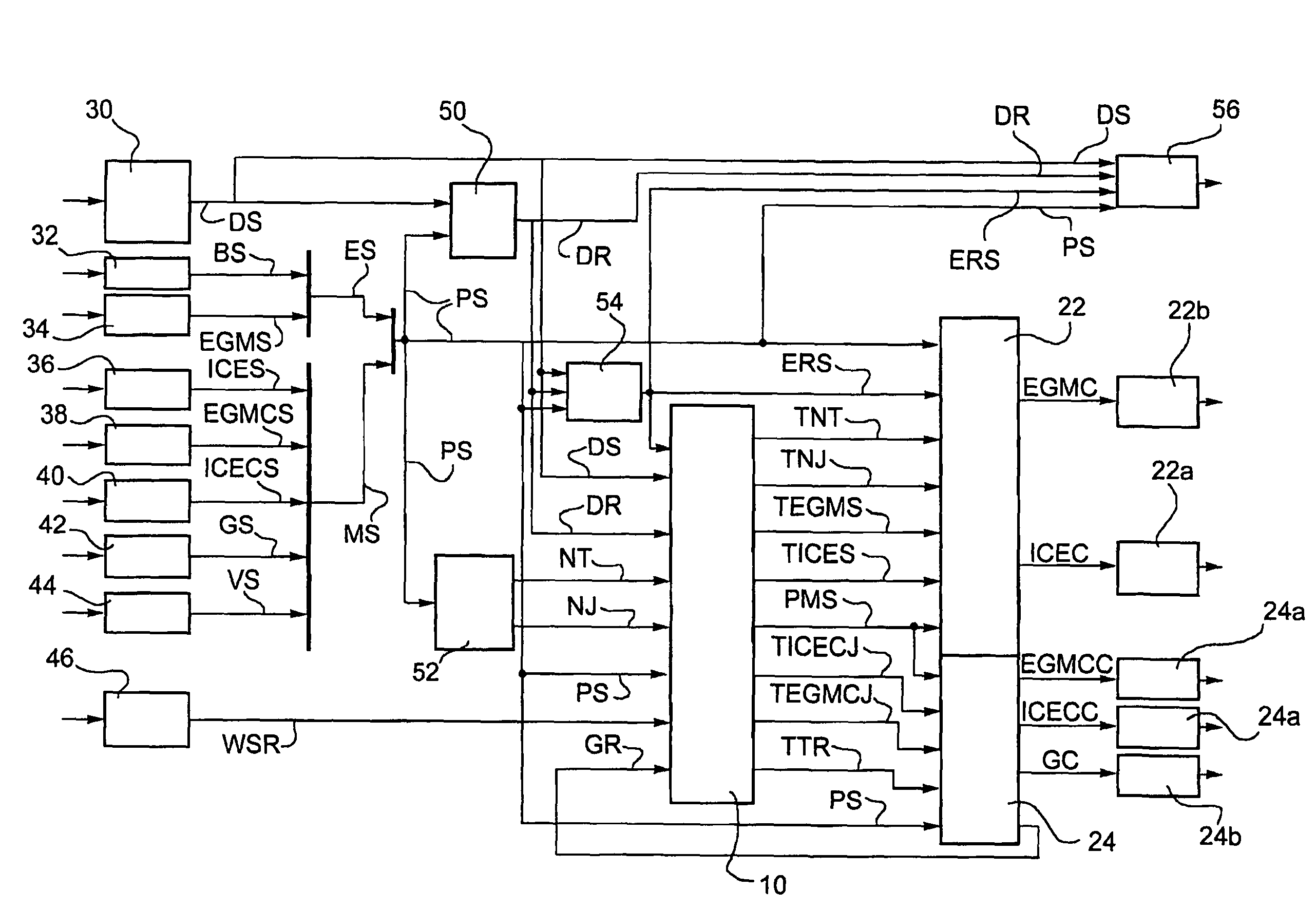
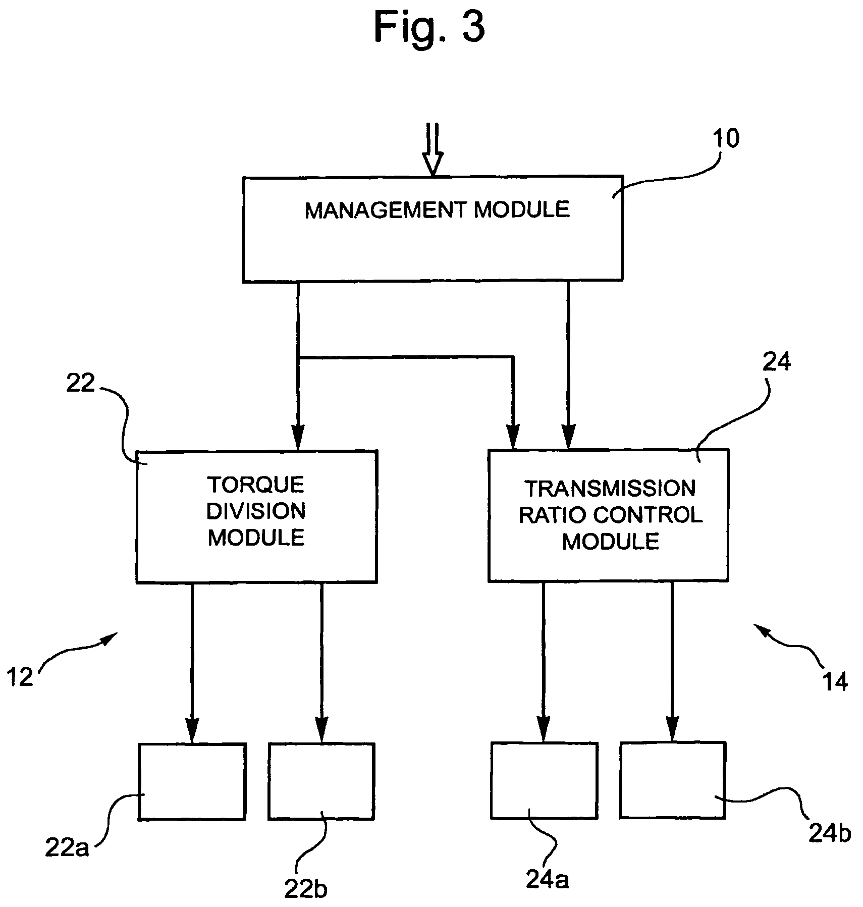
The invention is an integrated powertrain control system that combines the engine control and gearbox control in one system. This system can manage the power applied to the drive wheels, improving driving comfort and reducing fuel consumption and exhaust emissions. It can also be used for hybrid vehicles with an electric motor and internal combustion engine. The system uses a supervision module to receive driver commands and demands from accessory control systems, and provides commands to control modules and actuators for managing torque delivery and gear ratio. Overall, the invention achieves a true and proper integrated management of the engine and gearbox control systems.

Problems solved by technology

In the case of drivers who are not particularly expert, traction control, i.e. control of the torque effectively applied to the drive wheels and exchanged with the ground, is not in general optimal in such motor vehicles.
. . ) with negative effects on the speed and precision of response of the engine itself.
. . ), which therefore is not always able to satisfy the requirements of the gearbox.
Moreover, in a motor vehicle provided with a plurality of on board accessory systems for automatic traction control, for the aid of the driver, these can present torque demands to the engine simultaneously and in conflict with one another.
This, however, does not represent a real operative condition when starting from rest, in which the torque delivered by the engine is modulated by the clutch which is not completely engaged.

Method used


Image

  • Integrated power train control system for a motor vehicle
  • Integrated power train control system for a motor vehicle
  • Integrated power train control system for a motor vehicle

Examples


Embodiment Construction

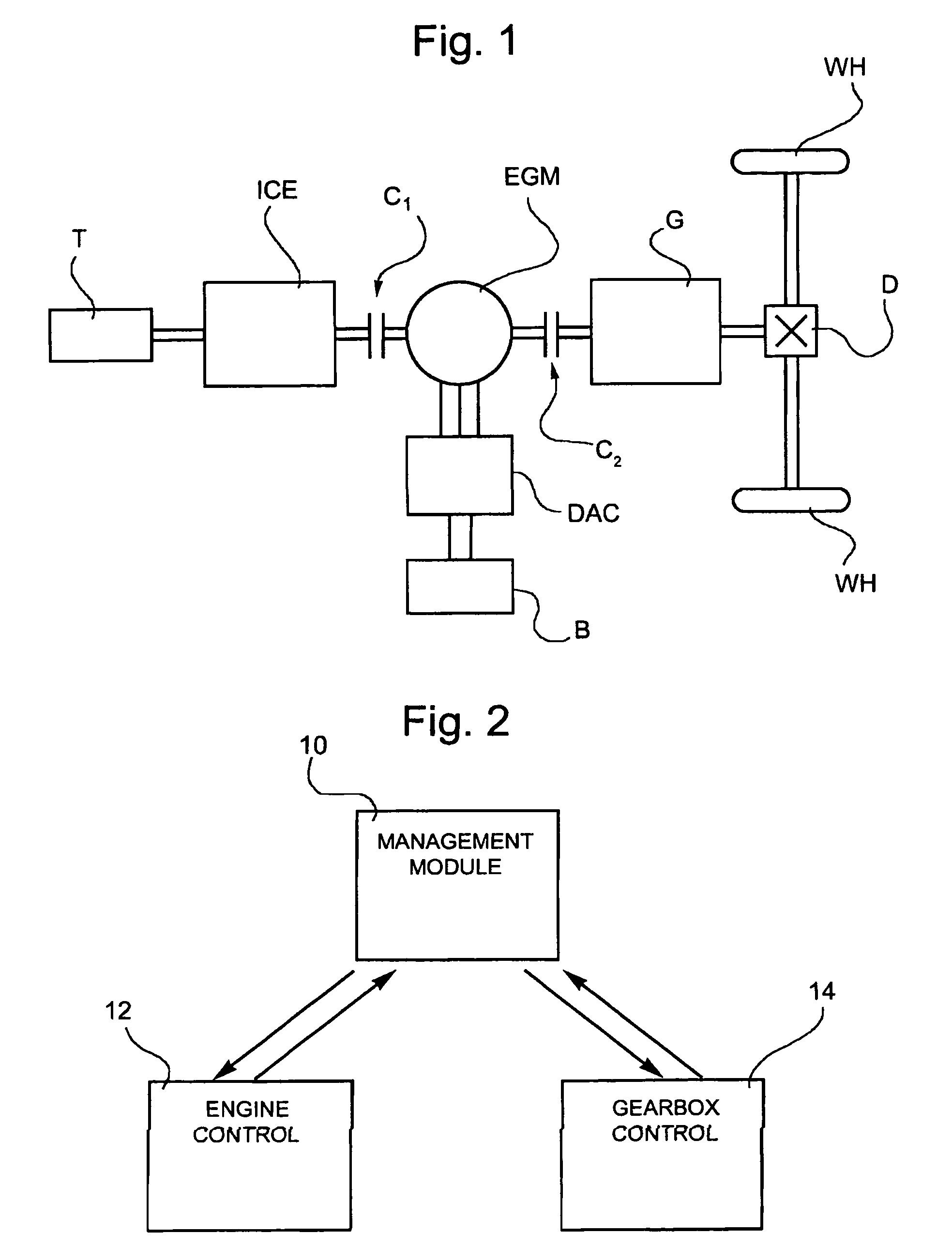
[0025]In FIG. 1 the reference ICE indicates an internal combustion engine of a motor vehicle having a fuel tank T. A reversible electric machine, indicated EGM, is disposed downstream of the internal combustion engine, to which it is coupled via a first clutch C1. By means of a second clutch C2 the electric machine and the thermal engine are coupled to a gearbox G of servo-assisted type, connected to a differential D for transmission of drive to the drive wheels WH of the vehicle.

[0026]In the example illustrated the electric machine EGM is coupled to an energy storage device such as a battery B through an electric energy conversion device DAC such as a DC / AC converter.

[0027]Naturally, the architecture illustrated refers to a currently-preferred embodiment and is only one of the possible arrangements, in which the reversible electric machine is shown on the same axis as the thermal engine and contributes to the traction, but it will be understood that an equivalent system could inclu...


PUM


Abstract

A powertrain control system for management and supervision of engine and servo-assisted gearbox control modules is arranged for determining the power to be applied to the drive wheels of the vehicle as a function of signals indicative of commands imparted by the driver, of the engine and gearbox state parameters and of possible requirements from the engine and gearbox control modules and supplementary on board vehicle traction / drive control systems; calculating data indicative of the torque to be delivered at the engine drive shaft, the torque transmissible by the clutch and the required transmission ratio, as a function of the determined value of the power to be applied to the drive wheels, of the state parameters and of the requirements of the engine and gearbox control modules and the traction / drive control systems; and transmitting the calculated data as signals to the engine and gearbox control modules.

Description

FIELD OF THE INVENTION[0001]The present invention relates to a powertrain control system for a motor vehicle, and more specifically to a control system of the type defined in the pre-amble of Claim 1.BACKGROUND OF THE INVENTION[0002]In the prior art the powertrain control in a motor vehicle takes place by interpreting the driver's command, imparted by means of the accelerator pedal, and translating this command into a request signal for a drive torque delivered by the engine itself as a function of the speed of rotation of the drive shaft. The power or the torque which is effectively applied to the drive wheels depends not only on the drive torque thus delivered from the engine, but also on the gear ratio selected at the gearbox.[0003]In a motor vehicle with a servo-assisted gearbox and architecture of manual type the commands imparted by the driver through the accelerator pedal, and possibly also the brake pedal, and the commands (via push button or lever) for selection of the tran...

Claims


Application Information

Patent Timeline
Patent Type & Authority Patents(United States)
IPC IPC(8): B60W10/04B60W10/08G06F19/00B60K6/48B60L50/16B60W10/10B60W10/18B60W30/18
CPCB60K6/48B60W10/06B60W10/08B60W10/11B60W10/18B60W10/20B60W30/188Y10T477/679B60L2240/443B60L2240/486B60W20/00B60W2510/0275B60W2510/0283B60W2510/0638B60W2510/0657B60W2510/1005B60W2510/1015B60W2510/104B60W2510/105B60W2510/244B60W2520/10B60W2520/105B60W2520/14B60W2520/26B60W2540/10B60W2540/12B60W2550/14B60W2550/142B60W2710/0644B60W2710/0666B60W2710/081B60W2710/083B60W2710/1005Y02T10/56Y02T10/6221Y02T10/6286Y10T477/688Y10T477/26Y10T477/24B60L2240/441Y02T10/84B60W2552/00B60W2552/15Y02T10/40Y02T10/62B60W2540/18B60W10/10B60W20/30
Inventor VAFIDIS, CONSTANTINOSMORRA, GIANLUCAOSELLA, GIANCARLOELIA, CORRADOEINAUDI, GIANPIEROPEROTTO, ALDOLUPO, SAVINO LUIGIPENNESE, MICHELE
Owner CENT RICERCHE FIAT SCPA
Learn More