Medical devices having multiple layers

a medical device and multi-layer technology, applied in the direction of catheters, blood vessels, metabolic disorders, etc., can solve the problems of devices having attendant mechanical requirements, and achieve the effect of high strength and non-complian

Active Publication Date: 2010-07-20
BOSTON SCI SCIMED INC
View PDF36 Cites 73 Cited by
  • Summary
  • Abstract
  • Description
  • Claims
  • Application Information

AI Technical Summary

Benefits of technology

[0008]An advantage of the present invention is that multilayer medical devices and medical device components can be provided, which are very thin and flexible, have very high strength, and are substantially non-compliant.
[0009]These and other aspects, embodiments and advantages of the present invention will become immediately apparent to those of ordinary skill in the art upon reading the disclosure to follow.BRIEF DESCRIPTION OF THE FIGURES
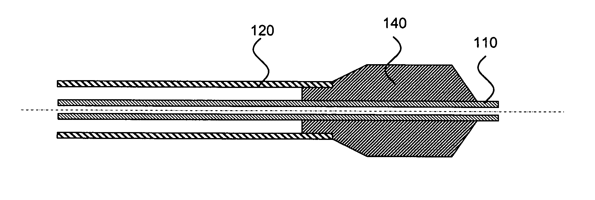
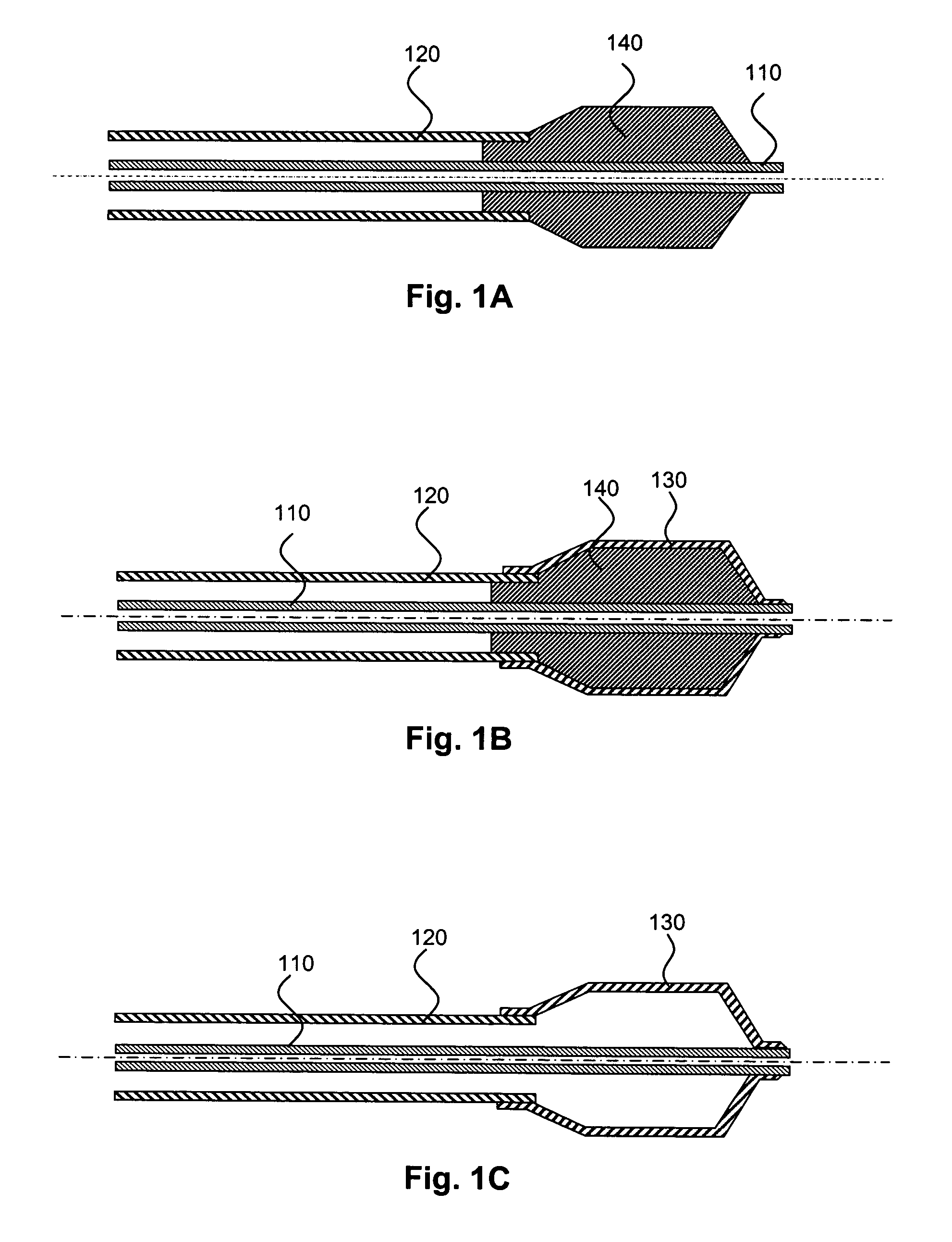
[0010]FIGS. 1A-1C are schematic illustrations that show a process for forming a balloon catheter, in accordance with an embodiment of the present invention.
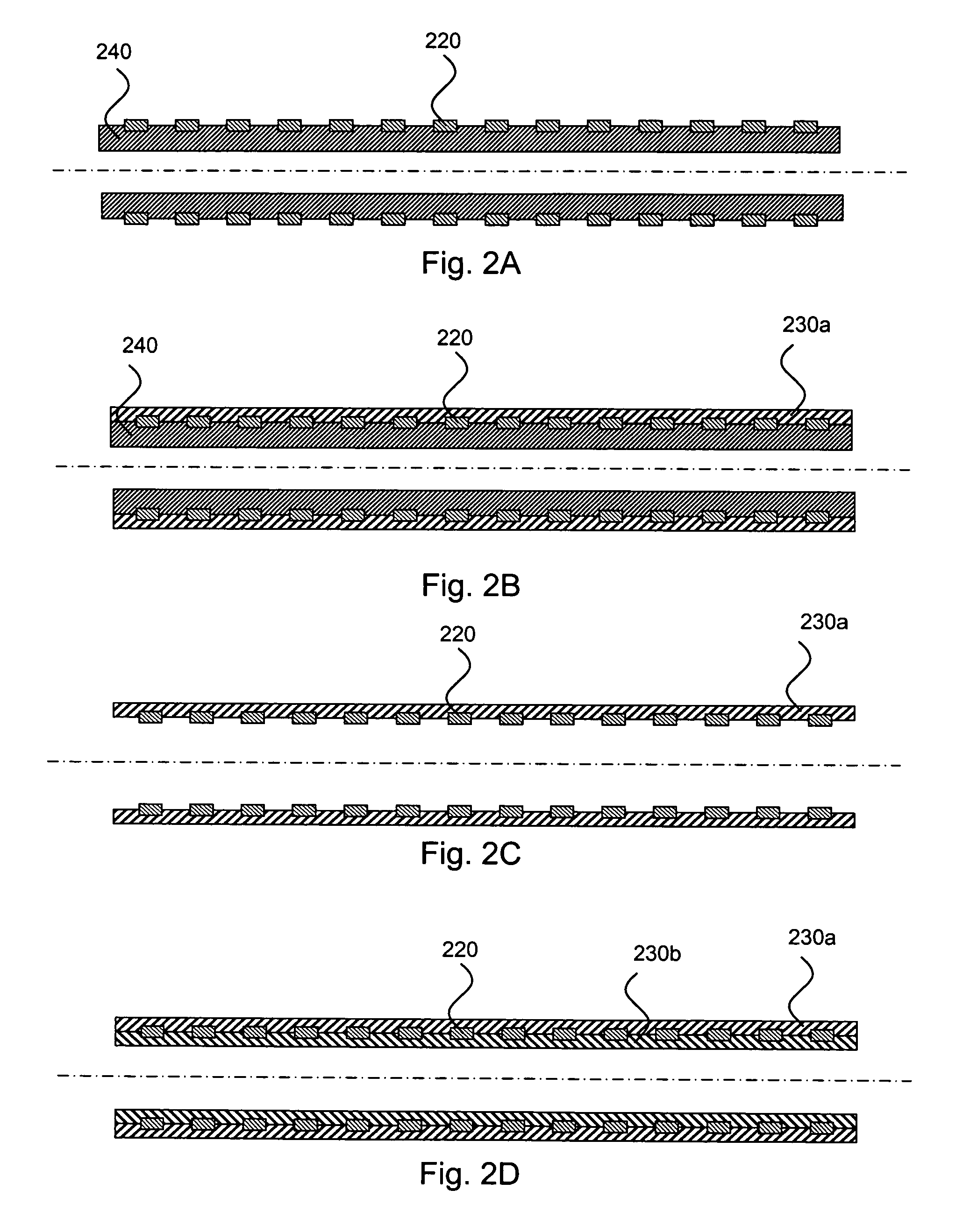
[0011]FIGS. 2A-2D are schematic illustrations that show a process for forming a stent draft coating, in accordance with another embodiment of the present invention.
[0012]FIGS. 3A-3C are schematic illustrations that show a process for forming a perfusion balloon catheter, in accordance with another embodiment of the present invention.

Problems solved by technology

As such theses devices have attendant mechanical requirements.

Method used


Image

  • Medical devices having multiple layers
  • Medical devices having multiple layers
  • Medical devices having multiple layers

Examples


example 1

[0095]A mold 3 mm in diameter of polyvinyl alcohol (PVOH) series C-5 (purchased from Adept Polymers Limited, London) is insert molded at 190° C. A metal core pin is embedded through the center of the mold.

[0096]The following solutions / suspensions are prepared: (1) Polyurethane Pellethane 70D (Dow Chemical, Midland, Mich.) in Tetrahydrofuran (THF) at a concentration of 5%; (2) polyethylenimine (PEI) (Aldrich) in water at a concentration of 1%; (3) polyacrylic acid (PAA) (Aldrich) in water at a concentration of 1%; and (4) carbon nanotubes (CNT) (Carbolex, Inc., Lexington, Ky., USA) in water at a concentration of 0.6%. The CNT are functionalized by refluxing them in nitric acid.

[0097]A first layer of the polyurethane is deposited (by dipping) on the PVOH core. Then, a layer of PEI is deposited on top of the polyurethane layer. After this, 204 layers are deposited by repeating the following sequence seventeen times: PAA-PEI-CNT-PEI-CNT-PEI-CNT-PEI-CNT-PEI-CNT-PEI. The PAA layers are in...

example 2

[0099]The procedures of Example 1 are followed, with the following changes: Instead of the core and the first polyurethane layer, an existing PEBAX 7233 single wall balloon (Boston Scientific Corp.) is used as a non-removable substrate. First, a layer of PEI deposited on the balloon. After this, 96 layers are deposited by following the following sequence eight times: PAA-PEI-CNT-PEI-CNT-PEI-CNT-PEI-CNT-PEI-CNT-PEI. As above, the PAA layers reinforce the electrostatic attraction between the layers.


PUM

PropertyMeasurementUnit
internal pressuresaaaaaaaaaa
diameteraaaaaaaaaa
diameteraaaaaaaaaa

Abstract

Described herein are medical devices which are configured for implantation or insertion into a subject, preferably a mammalian subject. The medical devices contain one or more multilayer regions, which contain: (a) one or more (typically a plurality of) charged nanoparticle layers and (b) one or more (typically a plurality of) charged polyelectroyte layers. Such multilayers have a number of desirable attributes, including high strength, non-compliance, and flexibility. Also described herein are methods of making such devices.

Description

FIELD OF THE INVENTION[0001]The present invention relates to the layer-by-layer assembly of multilayer regions for implantable and insertable medical devices, and more particularly, to the formation of multilayer regions that contain a plurality of nanoparticle layers for such devices.BACKGROUND OF THE INVENTION[0002]Various medical devices are known which are configured for implantation or insertion into a subject. As such theses devices have attendant mechanical requirements.[0003]For example, balloons mounted on the distal ends of catheters are widely used in medical treatment. A balloon may be used, for example, to widen a vessel into which the catheter is inserted or to force open a blocked vessel. The requirements for the strength and size of the balloon vary widely depending on the balloon's intended use and the vessel size into which the catheter is inserted. Perhaps the most demanding applications for such balloons are in balloon angioplasty (e.g., percutaneous transluminal...

Claims


Application Information

Patent Timeline
Patent Type & Authority Patents(United States)
IPC IPC(8): A61K9/16A61K9/14A61L27/34A61L31/08A61L31/10
CPCA61L29/085A61L29/16A61L2300/608A61L2300/624A61P23/00A61P29/00A61P35/00A61P3/06A61P7/02
Inventor CHEN, JOHN JIANHUAWEBER, JAN
Owner BOSTON SCI SCIMED INC
Why Eureka
Try Eureka