Surface-coated cutting tool with coated film having strength distribution of compressive stress

a cutting tool and coating technology, applied in the field of cutting tools, can solve the problems of poor wear resistance, reduced toughness, and reduced wear resistance, and achieve the effects of improving film chipping resistance, excellent wear resistance, and excellent toughness

Active Publication Date: 2010-07-20
SUMITOMO ELECTRIC HARDMETAL CORP +1
View PDF5 Cites 9 Cited by
  • Summary
  • Abstract
  • Description
  • Claims
  • Application Information

AI Technical Summary

Benefits of technology

[0038]Being structured as described above, the surface-coated cutting tool according to the present invention achieves both excellent toughness and excellent wear resistance as well as improved resistance to film chipping.
[0039]In particular, as can be seen in the strength distribution according to the first embodiment described above, the minimum compressive stress is attained at the surface of the coated film, so that wear resistance and resistance to film chipping are improved. In addition, the relative maximum point in the strength distribution of the compressive stress is formed in a portion inside the coated film close to the surface, and the compressive stress is maintained constant from the relative maximum point toward the bottom surface of the coated film, whereby toughness is drastically improved.
[0040]In addition, as can be seen in the strength distribution according to the second embodiment described above, the compressive stress at the surface of the coated film is smaller than that inside the coated film, so that wear resistance and resistance to film chipping are improved. Moreover, as the relative maximum point in the strength distribution of the compressive stress is formed in a portion inside the coated film close to the surface, development of cracking that has occurred on the surface of the coated film can be suppressed and toughness is drastically improved. In addition, the compressive stress continuously decreases from the relative maximum point toward the bottom surface of the coated film, whereby further excellent wear resistance can be achieved.
[0041]Furthermore, as can be seen in the strength distribution according to the third embodiment described above, the compressive stress at the surface of the coated film is smaller than that inside the coated film, so that wear resistance and resistance to film chipping are improved. Moreover, as the relative maximum point in the strength distribution of the compressive stress is formed in a portion inside the coated film close to the surface, excellent toughness is also achieved. Moreover, not only the relative maximum point but also the relative minimum point are provided, so that an effect to mitigate self-destruction of the coated film or stress such as impact is achieved in the vicinity of the relative minimum point, resistance to film chipping is drastically improved, and further excellent wear resistance can be obtained.
[0042]In addition, as can be seen in the strength distribution according to the fourth embodiment described above, the compressive stress at the surface of the coated film is smaller than that inside the coated film, so that wear resistance and resistance to film chipping are improved. Moreover, as the relative maximum point in the strength distribution of the compressive stress is formed in a portion inside the coated film close to the surface, excellent toughness is also achieved. Moreover, not only the relative maximum point but also the relative minimum point are provided, so that an effect to mitigate self-destruction of the coated film or stress such as impact is achieved in the vicinity of the relative minimum point, resistance to film chipping is drastically improved, and further excellent wear resistance can be obtained. Furthermore, a plurality of such relative maximum points and relative minimum points are formed, whereby toughness and wear resistance as well as resistance to film chipping are further improved.
[0043]As described above, the present invention has successfully achieved both excellent toughness and excellent wear resistance as well as improvement in resistance to film chipping, as a result of having strength distribution of the compressive stress characterized as above.

Problems solved by technology

If high wear resistance is required, however, toughness is lowered.
In other words, if maximum compressive stress is attained at the surface of the coated film, toughness is excellent whereas wear resistance is poor.
In contrast, if maximum compressive stress is attained at the surface of the base material, wear resistance is excellent whereas toughness is poor.
In particular, in the cutting tool attaining the maximum compressive stress at the surface of the coated film, the coated film tends to self-destruct due to that large compressive stress after the coated film is formed (after coating is finished) or when impact stress is applied.
Then, minute film peeling (hereinafter, referred to as film chipping) tends to occur, which adversely affects appearance of the cutting tool and cutting performance in high-precision process.

Method used


Image

  • Surface-coated cutting tool with coated film having strength distribution of compressive stress
  • Surface-coated cutting tool with coated film having strength distribution of compressive stress
  • Surface-coated cutting tool with coated film having strength distribution of compressive stress

Examples


first embodiment

Strength Distribution—First Embodiment

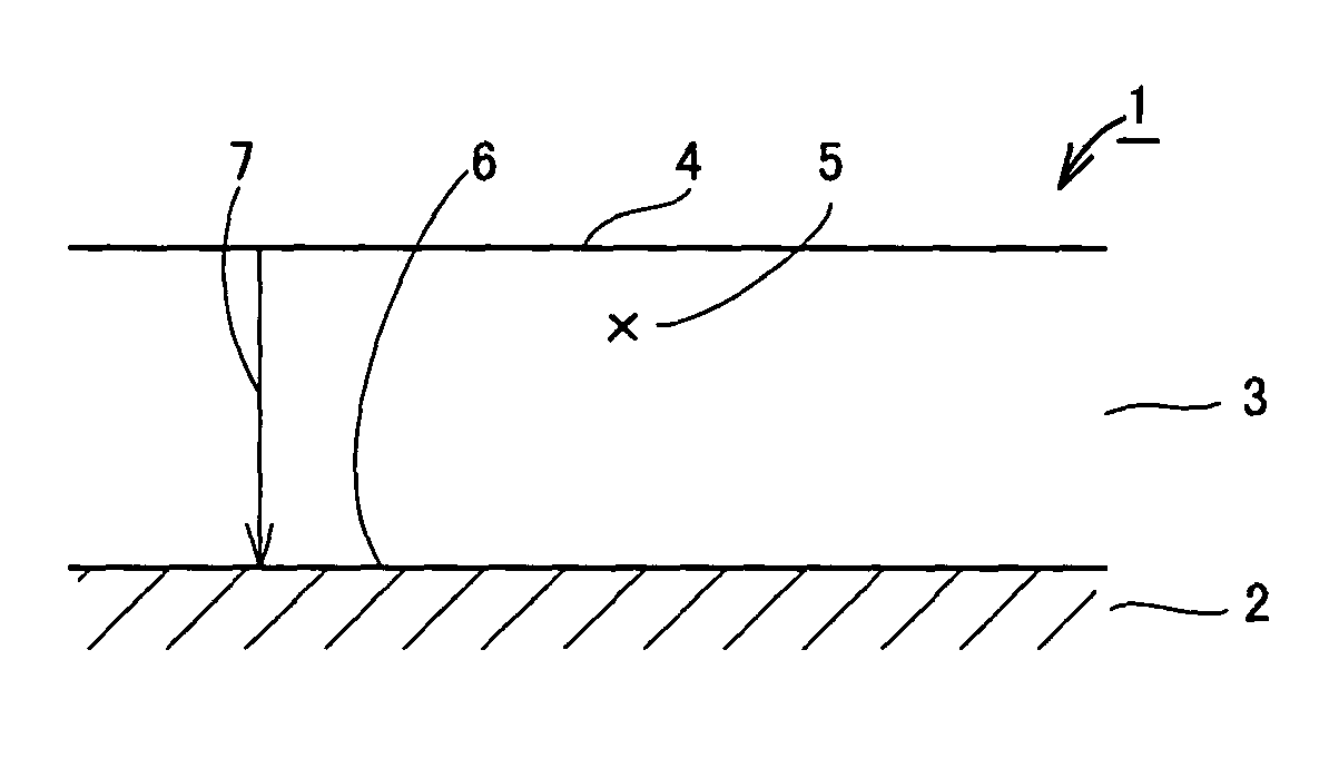
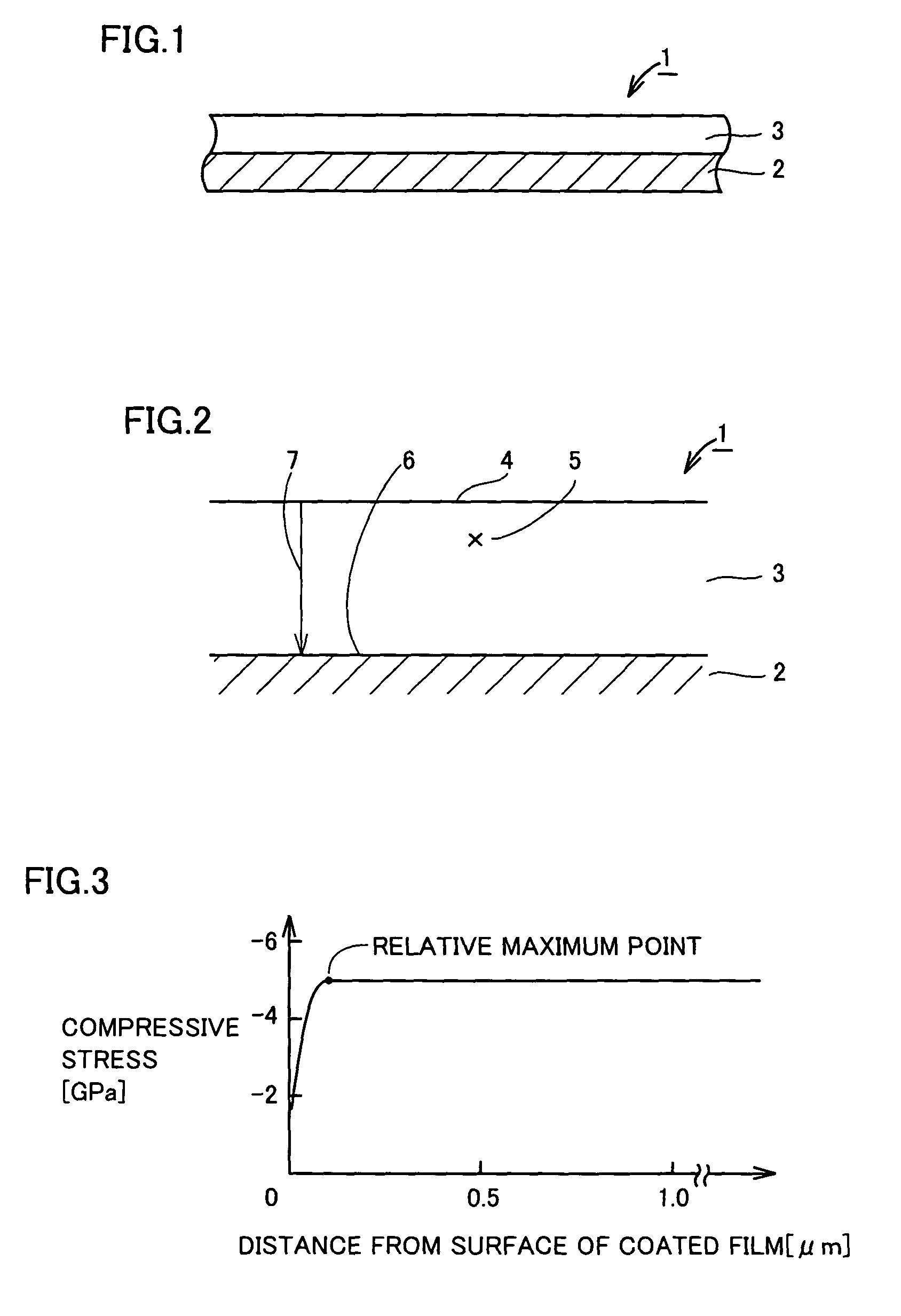
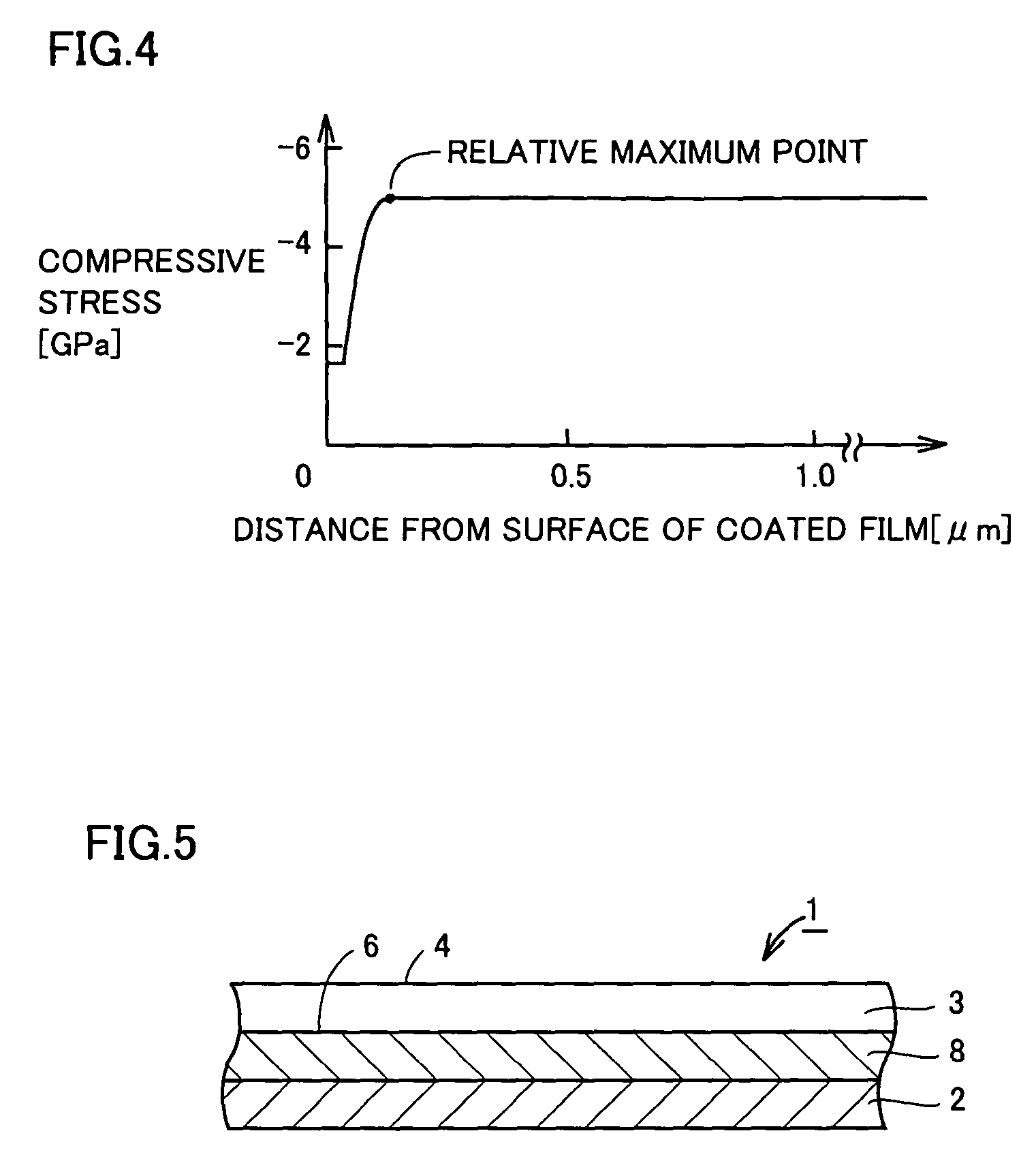
[0098]The first embodiment of the strength distribution is characterized in that the minimum compressive stress (in other words, the compressive stress attaining the smallest absolute value) is attained at the surface of the coated film, that the compressive stress continuously increases from the surface of the coated film toward the first intermediate point located between the surface of the coated film and the bottom surface of the coated film and attains a relative maximum point at the first intermediate point, and that the compressive stress maintains a constant value from the first intermediate point toward the bottom surface of the coated film.

[0099]This characteristic will be described in detail with reference to FIG. 2 and FIG. 3 showing the first embodiment of the strength distribution of the present invention. FIG. 3 is a graph showing the strength distribution, in which the abscissa represents a distance from the surface of the coated...

second embodiment

Strength Distribution—Second Embodiment

[0112]The second embodiment of the strength distribution is characterized in that the compressive stress at the surface of the coated film continuously increases from the surface of the coated film toward the first intermediate point located between the surface of the coated film and the bottom surface of the coated film and the compressive stress attains the relative maximum point at the first intermediate point, and that the compressive stress continuously decreases from the first intermediate point toward the bottom surface of the coated film.

[0113]This characteristic will be described in detail with reference to FIG. 2 and FIG. 6 showing the second embodiment of the strength distribution of the present invention. FIG. 6 is a graph showing the strength distribution, in which the abscissa represents a distance from the surface of the coated film in the direction of thickness of the coated film and the ordinate represents the compressive stres...

third embodiment

Strength Distribution—Third Embodiment

[0129]The third embodiment of the strength distribution is characterized in that the compressive stress at the surface of the coated film continuously increases from the surface of the coated film toward the first intermediate point located between the surface of the coated film and the bottom surface of the coated film and the compressive stress attains the relative maximum point at the first intermediate point, and that the compressive stress continuously decreases from the first intermediate point toward the second intermediate point located between the first intermediate point and the bottom surface of the coated film and attains the relative minimum point at the second intermediate point.

[0130]This characteristic will be described in detail with reference to FIG. 8 and FIG. 9 showing the third embodiment of the strength distribution of the present invention. FIG. 9 is a graph showing the strength distribution, in which the abscissa represen...


PUM

PropertyMeasurementUnit
compressive stressaaaaaaaaaa
thicknessaaaaaaaaaa
thicknessaaaaaaaaaa

Abstract

A surface-coated cutting tool according to the present invention includes a base material and a coated film formed on the base material. The coated film serves as an outermost layer on the base material and has compressive stress. The compressive stress is varied so as to have strength distribution in a direction of thickness of the coated film. The strength distribution is characterized in that the compressive stress at a surface of the coated film continuously increases from the surface of the coated film toward a first intermediate point located between the surface of the coated film and a bottom surface of the coated film and the compressive stress attains a relative maximum point at the first intermediate point.

Description

RELATED APPLICATIONS[0001]This application is the U.S. National Phase under 35 U.S.C. §371 of International Application No. PCT / JP2005 / 013182, filed on Jul. 15, 2005, which in turn claims the benefit of Japanese Application Nos. 2004-216349, 2004-220168, 2004-224092 and 2004-239826 filed on Jul. 23, 2004, Jul. 28, 2004, Jul. 30, 2004 and Aug. 19, 2004, respectively, the disclosures of which Applications are incorporated by reference herein.TECHNICAL FIELD[0002]The present invention relates to a cutting tool such as a drill, an end mill, a throw away tip for a drill, a throw away tip for an end mill, a throw away tip for milling, a throw away tip for turning, a metal saw, a gear cutting tool, a reamer, and a tap, and more particularly to a surface-coated cutting tool having a coated film for improving characteristics such as wear resistance formed on its surface (an outermost layer).BACKGROUND ART[0003]Conventionally, a hardmetal (a WC—Co alloy or an alloy obtained by adding a carbon...

Claims


Application Information

Patent Timeline
Patent Type & Authority Patents(United States)
IPC IPC(8): B32B9/00
CPCC23C14/0015C23C30/005C23C28/044C23C28/042Y10T428/24942Y10T428/31504B23B27/14B23B51/00B23C5/16C23C14/24
Inventor MORIGUCHI, HIDEKIFUKUI, HARUYOIMAMURA, SHINYAYAMAGUCHI, KOJIIIHARA, JUNJI
Owner SUMITOMO ELECTRIC HARDMETAL CORP
Why Eureka
Try Eureka