Cutting tool for high-quality high-efficiency machining and cutting method using the same

a cutting tool and high-efficiency technology, applied in the field of cutting tools, can solve the problems of reducing machining efficiency, affecting the surface roughness of finished surface, and unable to remove any affected layer, so as to improve machining efficiency, increase cutting depth, and widen the width

Active Publication Date: 2010-08-03
SUMITOMO ELECTRIC HARDMETAL CORP
View PDF19 Cites 30 Cited by
  • Summary
  • Abstract
  • Description
  • Claims
  • Application Information

AI Technical Summary

Problems solved by technology

But in this arrangement, the shape of the minor cutting edge tends to be transferred onto the finished surface in the form of corrugated feed marks, thus detrimentally influencing the surface roughness of the finished surface.
Although the surface roughness of the finished surface can be improved by reducing the depth of cut of the minor cutting edge and the feed rate of the tool, this solution will reduce the machining efficiency.
Thus, the finishing cutting edge and the wiper cutting edge are not cut into the workpiece, exceeding the depth of cut d of the cutting edge for rough cutting, and therefore cannot remove any affected layer.

Method used


Image

  • Cutting tool for high-quality high-efficiency machining and cutting method using the same
  • Cutting tool for high-quality high-efficiency machining and cutting method using the same
  • Cutting tool for high-quality high-efficiency machining and cutting method using the same

Examples


example 1

[0066]Cutting tool samples No. 1 to No. 42 shown in Tables 1A and 1B were prepared and evaluated for their cutting performance. Cutting tool samples No. 1 to No. 42 are formed of cBN-based sintered members of which the portions used for cutting have different shapes from each other. The cBN-based sintered members of each tool were formed by mixing cBN powder with binder powder comprising TiN and Al in a ball mill made of cemented carbide, and sintering the mixture in an ultrahigh pressure apparatus under a pressure of 5 GPa at 1500° C. Such cBN-based sintered members contained 60% by volume of cBN particles having an average particle diameter of 3 μm, the balance being Ti compounds primarily comprising TiN, Al compounds such as nitrides, borides or oxides of Al, and trace amounts of W and / or Co compounds.

[0067]Any of the cutting tools used in this evaluation test comprised a substrate made of cemented carbide, and cBN-based sintered members each having a thickness of 1.8 mm, a nose ...

example 2

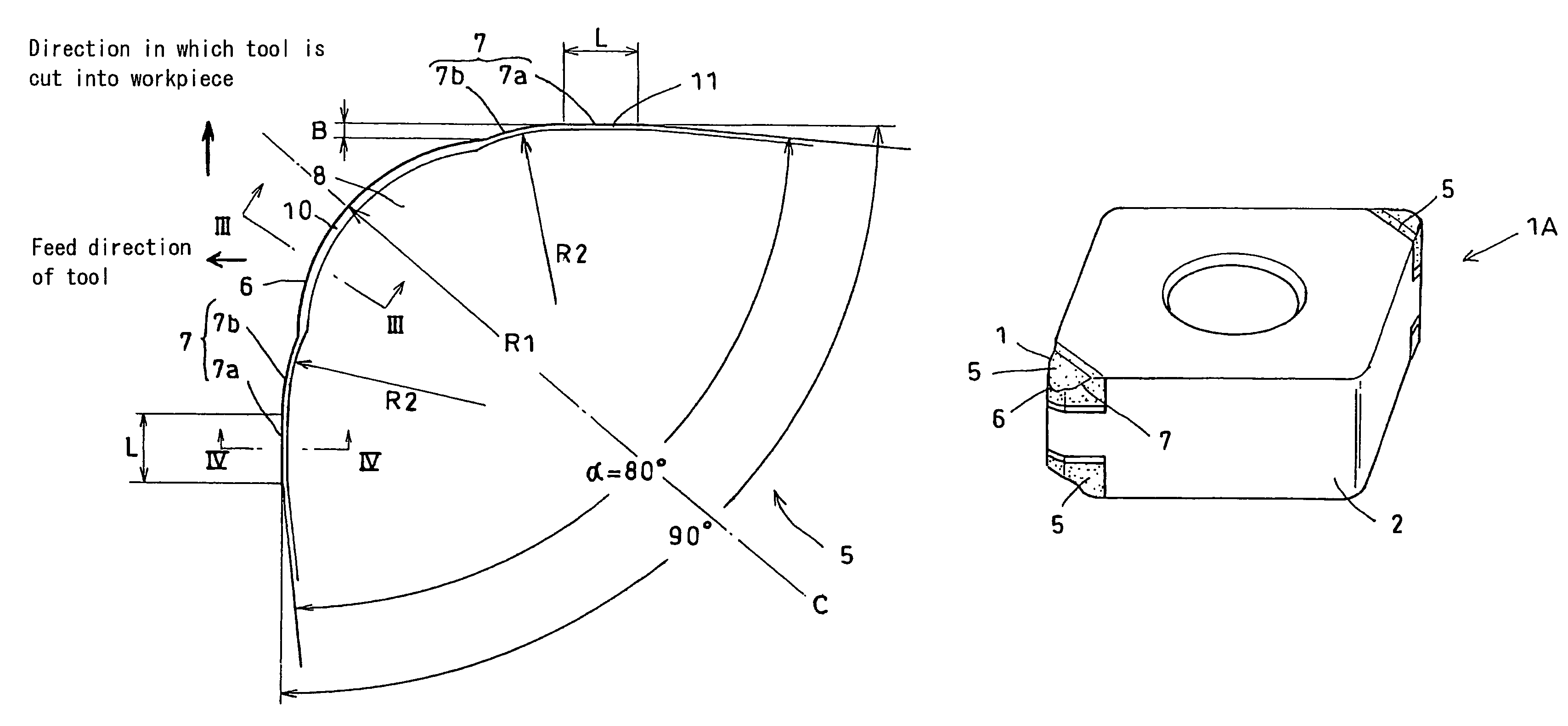
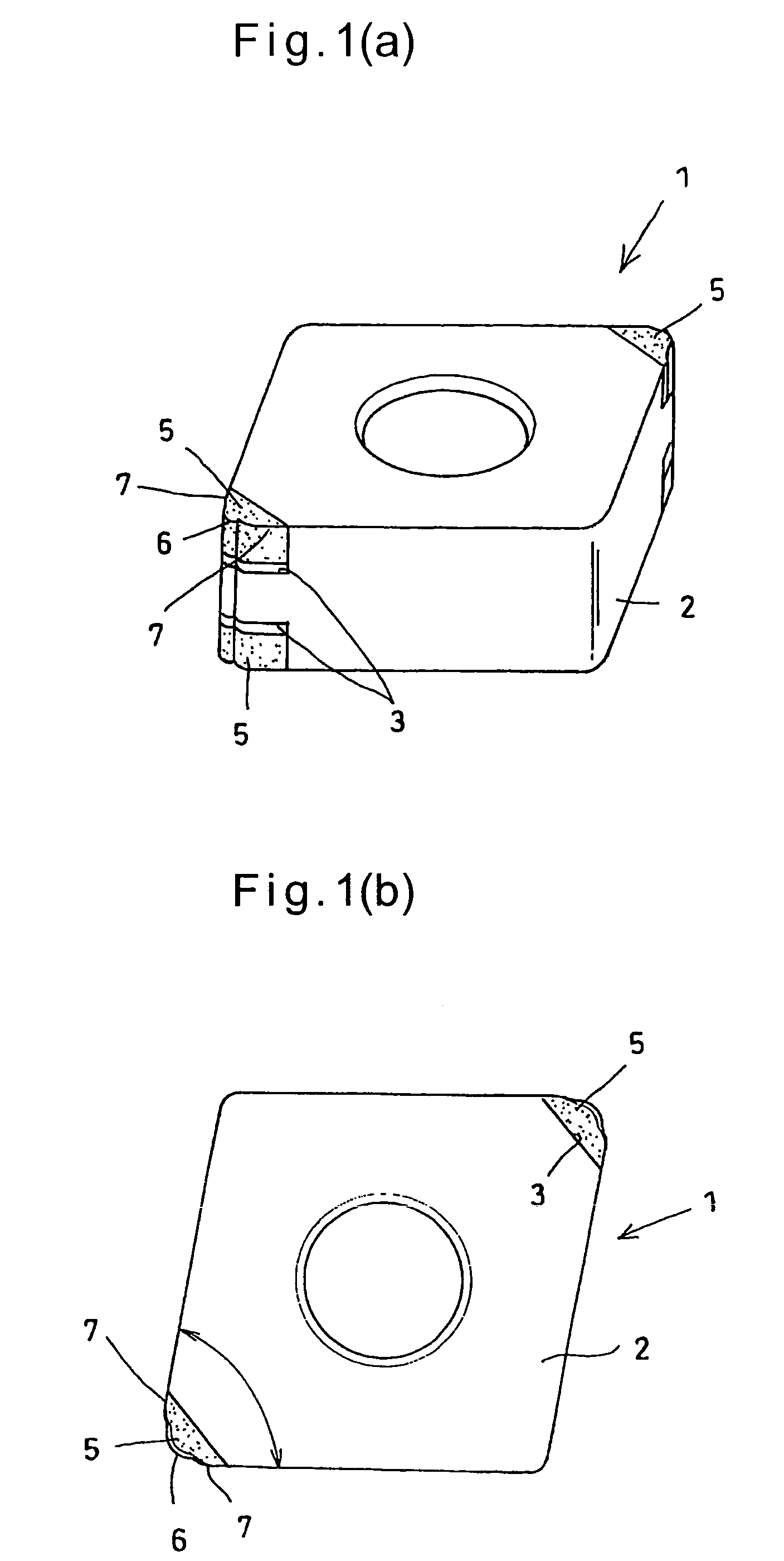
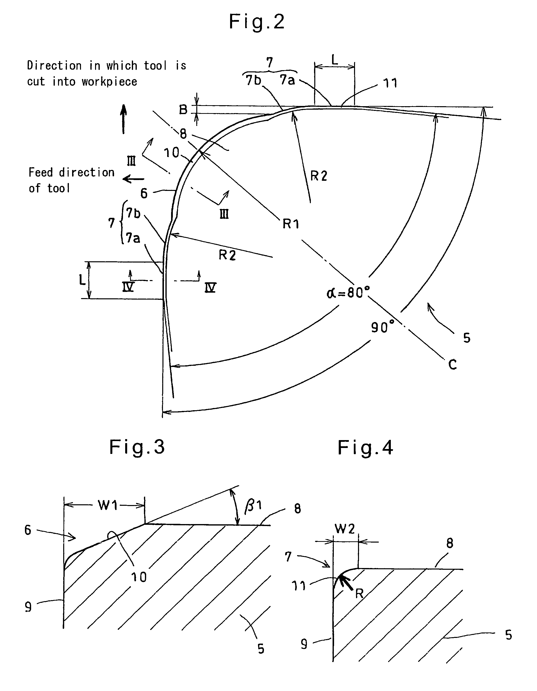
[0100]Cutting tool samples No. 51 to 69 shown in Table 2 were prepared. Any of the cutting tools used in EXAMPLE 2 comprised a substrate made of cemented carbide, and cBN-based sintered members each having a thickness of 1.8 mm, a nose angle α of 800 and a bottom length of 4 mm, including a carbide backing made of cemented carbide and brazed to one of the corners of the substrate. The cBN-based sintered members are inserts each classified into CNMA120408, CNMA120412 or CNMA120416 under ISO and having a cutting edge comprising a finishing cutting edge forming an arcuate nose, and superfinishing cutting edges which characterize the present invention. The cBN-based sintered members were of the same composition as those used in EXAMPLE 1.

[0101]The finishing cutting edge of any sample had a chamfer angle of 25° and a chamfer width of 0.13 mm (the border between the chamfer and the flank being rounded with a radius of curvature of 0.01 mm). The chamfers of the superfinishing cutting edges...


PUM

PropertyMeasurementUnit
width W2aaaaaaaaaa
thermal conductivityaaaaaaaaaa
widthaaaaaaaaaa

Abstract

It is an object to provide a cutting tool which can perform high-quality, high-efficiency machining of a workpiece such as hardened steel.The cutting tool includes a finishing cutting edge 6 which initially cuts into the workpiece, and superfinishing cutting edges 7 for finishing the workpiece cut by the finishing cutting edge. The superfinishing cutting edges 7 project from the finishing cutting edge by a predetermined amount B in such a direction that the depth of cut of the superfinishing cutting edges increases. Each superfinishing cutting edge includes a burnishing portion 7a having a predetermined width L in the feed direction of the tool, and a wiper portion 7b. The superfinishing cutting edges 7 burnish the finished surface formed by the finishing cutting edge, while removing a affected layer formed by the finishing cutting edge.

Description

RELATED APPLICATIONS[0001]This application is the U.S. National Phase under 35 U.S.C. §371 of International Application No. PCT / JP2006 / 306438 filed on Mar. 29, 2006, which in turn claims the benefit of Japanese Application No. 2005-293991, filed on Oct. 6, 2005, the disclosures of which Applications are incorporated by reference herein.TECHNICAL FIELD[0002]This invention relates to a cutting tool capable of performing high-quality, high-efficiency cutting of (metal) workpieces, and specifically a cutting tool which can particularly advantageously cut hardened steel, and a method of cutting workpieces using such a cutting tool.BACKGROUND ART[0003]Cutting tools capable of performing high-quality, high-efficiency cutting of workpieces are disclosed in the below-mentioned Patent documents 1 and 2.[0004]The cutting tool disclosed in Patent document 1 is used for machining hardened steel and includes a major cutting edge which performs a major portion of the necessary cutting, and a minor...

Claims


Application Information

Patent Timeline
Patent Type & Authority Patents(United States)
IPC IPC(8): B23B3/00B23C5/16
CPCB23B27/145B23B27/1622Y10T407/23B23B2200/0433B23B2200/201B23B2200/204B23B2200/208B23B2200/242B23B2200/245B23B2200/28B23B2220/24B23B2222/04B23B2226/125B23B2226/315B23B2240/08B23B2270/26Y10T407/1962Y10T82/10Y10T407/27Y10T83/0591B23D35/002
Inventor KURODA, YOSHIHIROKUKINO, SATORUOKAMURA, KATSUMIFUKAYA, TOMOHIRO
Owner SUMITOMO ELECTRIC HARDMETAL CORP
Why Eureka
Try Eureka