
Manufacturing method of thin-wall bearing and method for machining thin-wall inner ring/outer ring of the thin-wall bearing as well as precise flexible bearing

a technology of thin-wall bearings and manufacturing methods, which is applied in the field of machine tools, can solve the problems of reducing the manufacturing efficiency of thin-wall rings, and difficulty in obtaining high manufacturing precision. , to achieve the effect of low cost, low efficiency and low precision

Active Publication Date: 2018-11-15
SHANGHAI F&S BEARING TECH
View PDF0 Cites 7 Cited by
  • Summary
  • Abstract
  • Description
  • Claims
  • Application Information

AI Technical Summary

Benefits of technology

The present invention improves the thin-wall bearing ring cutting processing by reducing the number of processes, increasing efficiency, and decreasing cost and low precision. The reinforcement of the ring is done from the blank feeding, which results in quality and efficiency throughout the manufacturing process. This includes the advantages of improved turning processing efficiency, reduced scrap rate, and greater precision machining after heat treatment. Additionally, the reinforced rings have a high accuracy foundation during grinding, hard turning, and superfinishing phases, leading to high machining accuracy and a reduction in processing steps and cost.

Problems solved by technology

Thus, the thin-wall bearings are generally used in precise things, typically, such as harmonic reducer flexible bearings and RV reducer bearings, cross roller bearings used in lumbar and crotch of the robots for industrial robots, but because of the thin wall and narrow width of the thin-wall bearing, it is very easy to deform in all aspects of processing and it is very difficult to obtain high manufacturing precision.
These measures said above can improve the manufacturing accuracy of the ring, but the degree of improvement is limited.
And these measures has greatly reduced the manufacturing efficiency of the thin-wall rings, improved the thin-walled rings and thus increased the manufacturing costs of thin-wall bearings.
Thin-wall rings are difficult to obtain high machining accuracy and the increasing precision requirements of the main machine for thin-wall bearings have created a prominent pair of contradictions, which has severely constrained the further improvement of operation accuracy and limit speed of the main machine with lightweight.

Method used


Image

  • Manufacturing method of thin-wall bearing and method for machining thin-wall inner ring/outer ring of the thin-wall bearing as well as precise flexible bearing
  • Manufacturing method of thin-wall bearing and method for machining thin-wall inner ring/outer ring of the thin-wall bearing as well as precise flexible bearing
  • Manufacturing method of thin-wall bearing and method for machining thin-wall inner ring/outer ring of the thin-wall bearing as well as precise flexible bearing

Examples


embodiments 1 to 3

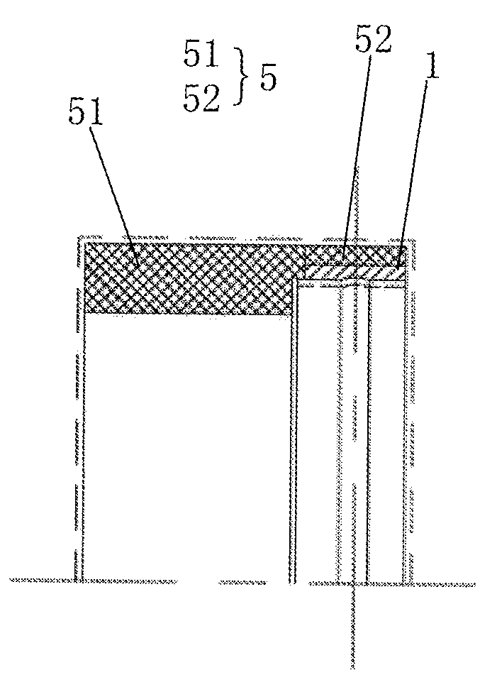
[0049]Referring to FIG. 3 to FIG. 5 comprehensively, in the illustrated embodiments 1 to 3, the following features are further defined: in the step S1, further reinforcing is performed along the radial direction of the thin-wall ring, and the reinforcing part reinforces on the outer circular surface of the thin-wall ring provided in step S0. Further, in these three embodiments, in Example 1 and Example 2,

[0050]In the step S0, the thin-wall ring is provided with a raceway. In the step S3, the hard turning, grinding and superfinishing process to the reinforcing ring further includes:

grinding two end surfaces, the inner circular surface and the outer circular surface and raceway surface of the reinforcing ring;

superfinishing the raceway surface after grinded, and after that;

hart turning the outer circular surface of the reinforcing ring to remove the reinforcing part 5 of the radial reinforcement.

[0051]Further distinguishing Embodiment 1 and Embodiment 2, in Embodiment 1, what machined...

first embodiment

[0054]It is a machining method of radial reinforcement of the outer ring of the thin-wall bearing.

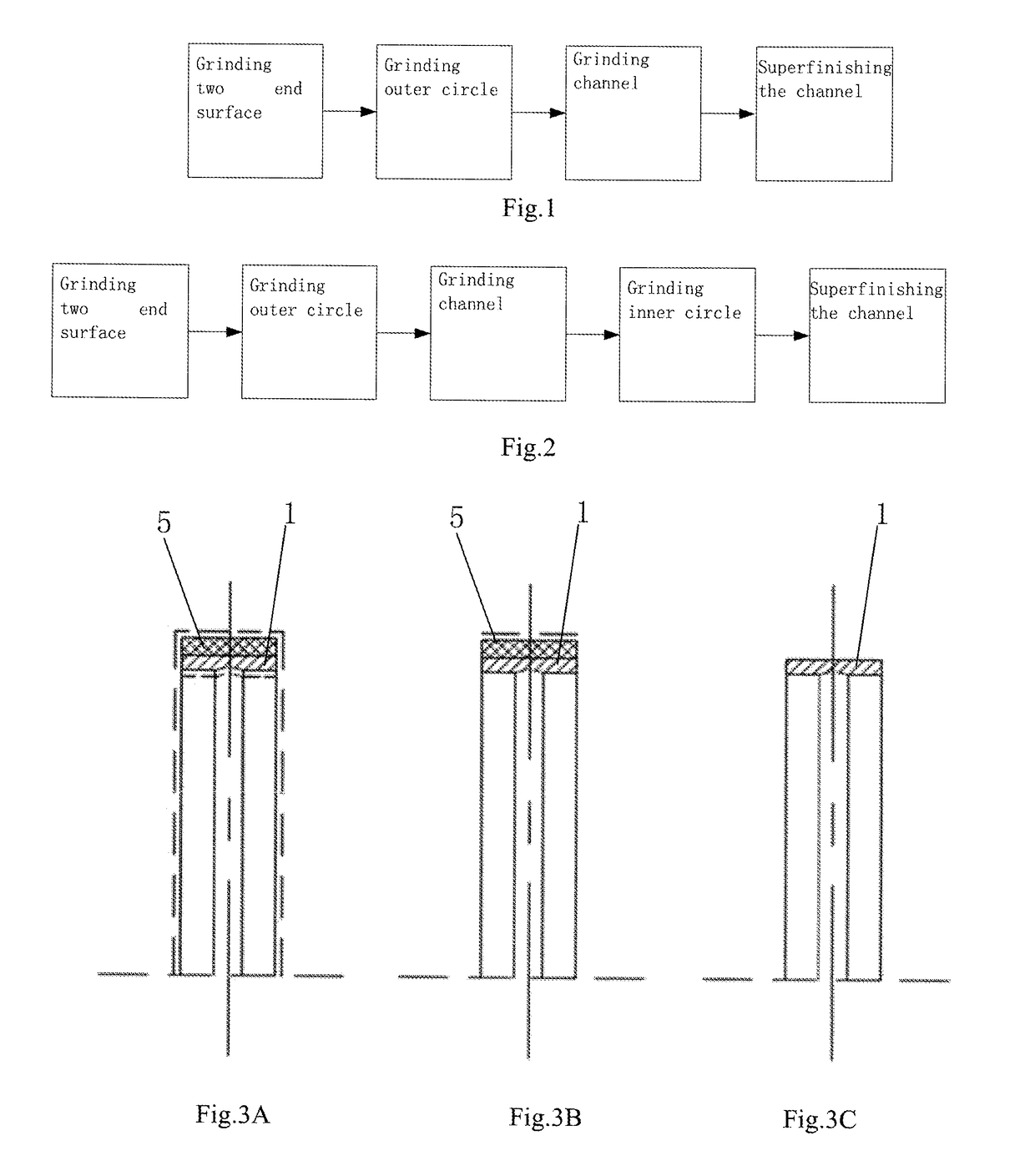
[0055]As shown in FIGS. 3A, 3B, and 3C, FIG. 3A shows a roughcast of a thin-walled outer ring 1 before being reinforced in radial direction and finishing. FIG. 3B is a semi-finished outer ring of the radial reinforced outer ring of FIG. 3A processed through several steps. FIG. 3C shows a finished thin-wall outer ring 1 formed by machining the semi-finished outer ring of FIG. 3B. The radial reinforcement of the outer ring is to increase the outer diameter along the full width of the outer ring, and the wall thickness of the outer ring after reinforcement is 1.2 to 11 times of that before reinforcement, that is, the wall thickness of the reinforcing part is 0.2 to 10 times the wall thickness of the thin-wall ring; processing sequence is as follows:

[0056]FIG. 3A shows the radial reinforcing to the blank outer ring→1: Grinding two end surfaces→2: Grinding outer circle→3: Grinding inner circ...

second embodiment

[0059]It is a machining method of radial reinforcement of the inner ring of the thin-wall bearing.

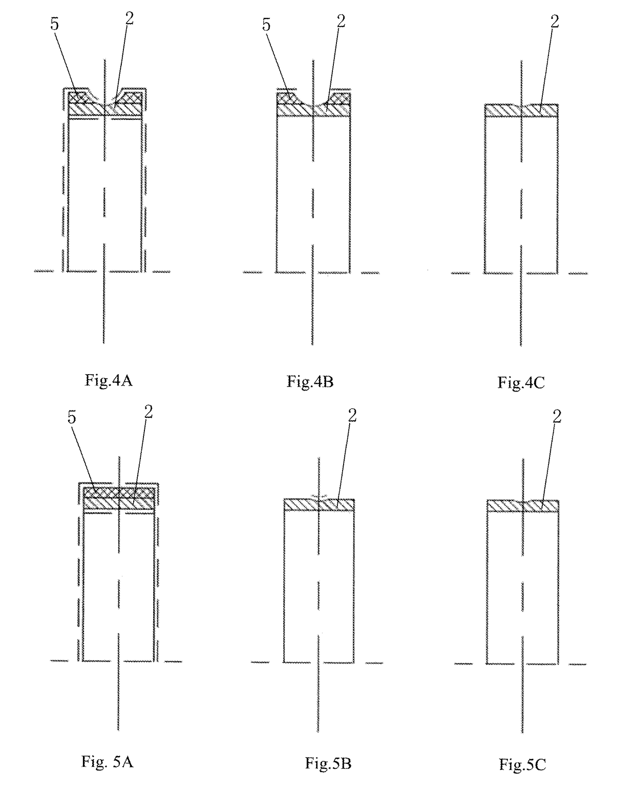
[0060]As shown in FIGS. 4A, 4B, and 4C, FIG. 4A shows a rough cast of a thin-walled inner ring before being reinforced in radial direction and finishing. FIG. 4B is a semi-finished inner ring of the radial reinforced inner ring of FIG. 4A processed through several steps. FIG. 4C shows a finished thin-wall inner ring formed by machining the semi-finished inner ring of FIG. 4B. The radial reinforcement of the inner ring is to increase its outer diameter along the full width of the inner ring (the channel part is left with a circular arc extension vacancy), and the wall thickness of the inner ring after reinforcement is 1.2 to 11 times that before reinforcement; a processing sequence is as follows:

[0061]FIG. 4A the Radial reinforced blank of the inner ring→1: Grinding two end surfaces→2: Grinding outer circle (which is channel rib)→3: Grinding channel→4: Grinding inner circle→5: Superfinis...


PUM

PropertyMeasurementUnit
Lengthaaaaaaaaaa
Thicknessaaaaaaaaaa
Diameteraaaaaaaaaa

Abstract

The invention provides a manufacturing method for thin-wall bearing and a method for machining a thin-wall inner ring / outer ring as well as a precision flexible bearing. The method for machining the thin-wall inner ring / outer ring comprises the following steps of: S0. providing a thin-wall ring with machining allowance left; S1: reinforcing along the radial direction and / or axial direction of the thin-wall ring; S2: carrying out quenching-tempering heat treatment on the reinforcing ring obtained by reinforcement in the S1; S3: carrying out corresponding grinding, hard cutting and super finishing on the reinforcing ring after receiving heat treatment, which includes removal of the machining allowance and a reinforcing part obtained by reinforcement in the S1, thereby obtaining finished thin-wall ring product. The thin-wall ring reinforced machining method substantially reduces and even avoids deformation of the thin-wall ring in all manufacturing links, thereby obtaining very high machining precision. The precision thin-wall bearing and the precision flexible bearing can be manufactured by fitting of the precision thin-wall ring and a precision rolling body.

Description

TECHNICAL FIELD[0001]The present invention relates to the field of machinery, in particular to a manufacturing process of a thin-wall bearing.BACKGROUND ART[0002]In the prior art, if outer diameter of a bearing is D, inner diameter is d, then a radial section size is (D−d) / 2. In general, a rolling bearing having a radial cross-sectional dimension less than ¼ of the inner diameter, or less than ⅙ of the outer diameter, or less than twice the diameter of the rolling element can be regarded as a thin-wall rolling bearing. The weight of thin-wall bearings is generally less than ½ of the weight of the ultra-light series bearing with the same inner diameter. The weight of some types of thin-wall bearings is even less than 1 / 40 of the weight of ultra-light series bearings with the same inner diameter. Thus we can know that the wall is so thin and the width is so narrow.[0003]With the development of main machine in the direction of integration, light weight, intelligence, and low power cons...

Claims


Application Information

Patent Timeline
IPC IPC(8): F16C33/64
CPCF16C33/64B23P15/003F16C1/00F16C19/06F16C2240/40F16C2322/59
Inventor ZHAO, SICHENGZHAO, LIANCHUNCHEN, SHUYING
Owner SHANGHAI F&S BEARING TECH
Learn More