Transportable blanket roller

a blanket roller and blanket technology, applied in the field of webtype materials, can solve the problems of low softening and combustion temperature of plastic sheets, and temperature limits, so as to reduce manufacturing, shipping and storage, and reduce manufacturing costs. , the effect of reducing the number of shops

Inactive Publication Date: 2010-08-03
PIEPGRAS DOUGLAS D
View PDF27 Cites 3 Cited by
  • Summary
  • Abstract
  • Description
  • Claims
  • Application Information

AI Technical Summary

Benefits of technology

[0012]Exemplary embodiments of the present invention solve inadequacies of the prior art by providing a readily assembled and disassembled transportable insulated blanket roller, and a method by which insulated blankets may be rolled, bound, stored or transported in the rolled and bound state, and unrolled for use.
[0015]In a third manifestation, the invention is a method of efficiently using at least one insulated blanket at a construction site to insulate a mass. According to the method, at least one rolled insulated blanket is stored at a first location. The at least one rolled insulated blanket is transported to a second location. The at least one rolled insulated blanket is slid onto a bifurcated roller. The at least one rolled insulated blanket is unrolled from the bifurcated roller to form at least one unrolled insulated blanket. The at least one unrolled insulated blanket is positioned relative to the mass to thermally insulate the mass at least in part from a surrounding environment. The at least one unrolled insulated blanket is rolled onto the bifurcated roller to thereby restore the at least one unrolled insulated blanket to the at least one rolled insulated blanket. The at least one rolled insulated blanket is slid off of the bifurcated roller. The at least one rolled insulated blanket is transported to the first location.OBJECTS OF THE INVENTION
[0016]A first object of the invention is to alleviate much of the inconvenience associated with rolling up and transporting concrete curing blankets on construction job sites. A second object of the invention is to meet certain design criteria in function and use. Another object of the present invention is to maintain ease of manufacturing, shipping and storage. This will desirably require minimal shop fabrication and minimal parts, to enable shipment to a purchaser in a disassembled state, while initial assembly requires only common tools and no significant assembly skills. As a corollary thereto, it is an object of the present invention after initial assembly that the apparatus may be assembled and disassembled rapidly without the use of any tools, or less preferably with only minimal or common tools, while achieving a correct length so that the apparatus may lay flat in the bed of a pickup truck. A further object of the invention is to easily support the apparatus within a vehicle hitch receiver or alternatively upon fabricated support which might readily be otherwise provided. Yet another object of the present invention is to allow a user to stand comfortably with the operating handle at a height that is easy to use, and turned at an angle relative to the back of a pick up truck such that the main support tube and blanket being rolled are away from the vehicle sufficiently to minimize the chance of damaging contact therebetween.

Problems solved by technology

Such is the case when concrete is poured during weather too cold or too hot to facilitate proper curing.
While it is known to incorporate various additives directly into concrete that will improve the curing and setting of the concrete at lower temperatures or higher temperatures, there are still temperature limits within which optimum curing and optimum ultimate strength will be achieved.
This method has several drawbacks, not the least of which is the relatively soft and fragile nature of the polyethylene, which may tear or come loose from anchors.
Further, the plastic sheet has quite low softening and combustion temperatures, so a heater may inadvertently melt or even ignite the sheeting.
Tears, separation, melting or combustion will expose the concrete directly to the temperatures that were to be avoided, and can even be the source of fire that could damage not only the concrete but also surrounding construction.
The need for heaters, air conditioners, or other devices is also undesirable since these devices must also be transported to and left at the job site, where they may be stolen or may fail.
In either case, not only will the concrete suffer the undesired fate which the sheeting was to prevent, the shelter above the concrete may in fact exacerbate the problem.
For example, if the air space is being cooled on a hot sunny day, failure of the cooling equipment may result in the plastic forming a greenhouse over the concrete, which could lead to temperatures even greater than if the plastic were never used at all.
Unfortunately, and in spite of the many benefits and advantages of insulated blankets, there remain a number of drawbacks that have heretofore limited the desirability of using them in building and construction projects.
One limitation is the average size of an insulated blanket, which in the industry may typically be five and one-half feet wide and range in length from eight to twenty-five feet.
Unfortunately, the large size also makes an insulated blanket very difficult for one worker to handle or carry if the blanket is extended or even folded.
Similar problems arise during transport of insulated blankets.
Insulated blankets, owing to their size, are generally too large to be secured in the bed of a pick-up truck, even when folded in the ordinary manner.
Even when positioned on the trailer properly, a person will often still have trouble reliably securing the blankets to the trailer with tie-down straps or the like without harming the blankets.
Once again, this added time loading and securing the blankets limits the number of applications where a builder will even consider using these blankets.
While illustrating potentially useful and beneficial carts, each of these apparatus undesirably require the transport of the relatively large and complex cart to and from location, and the expense of fabrication associated with such a cart.
These patents do not provide any apparatus that would be of use in both unrolling and rolling insulated blankets or other like materials used in the building and construction industry.

Method used


Image

  • Transportable blanket roller
  • Transportable blanket roller
  • Transportable blanket roller

Examples


Embodiment Construction

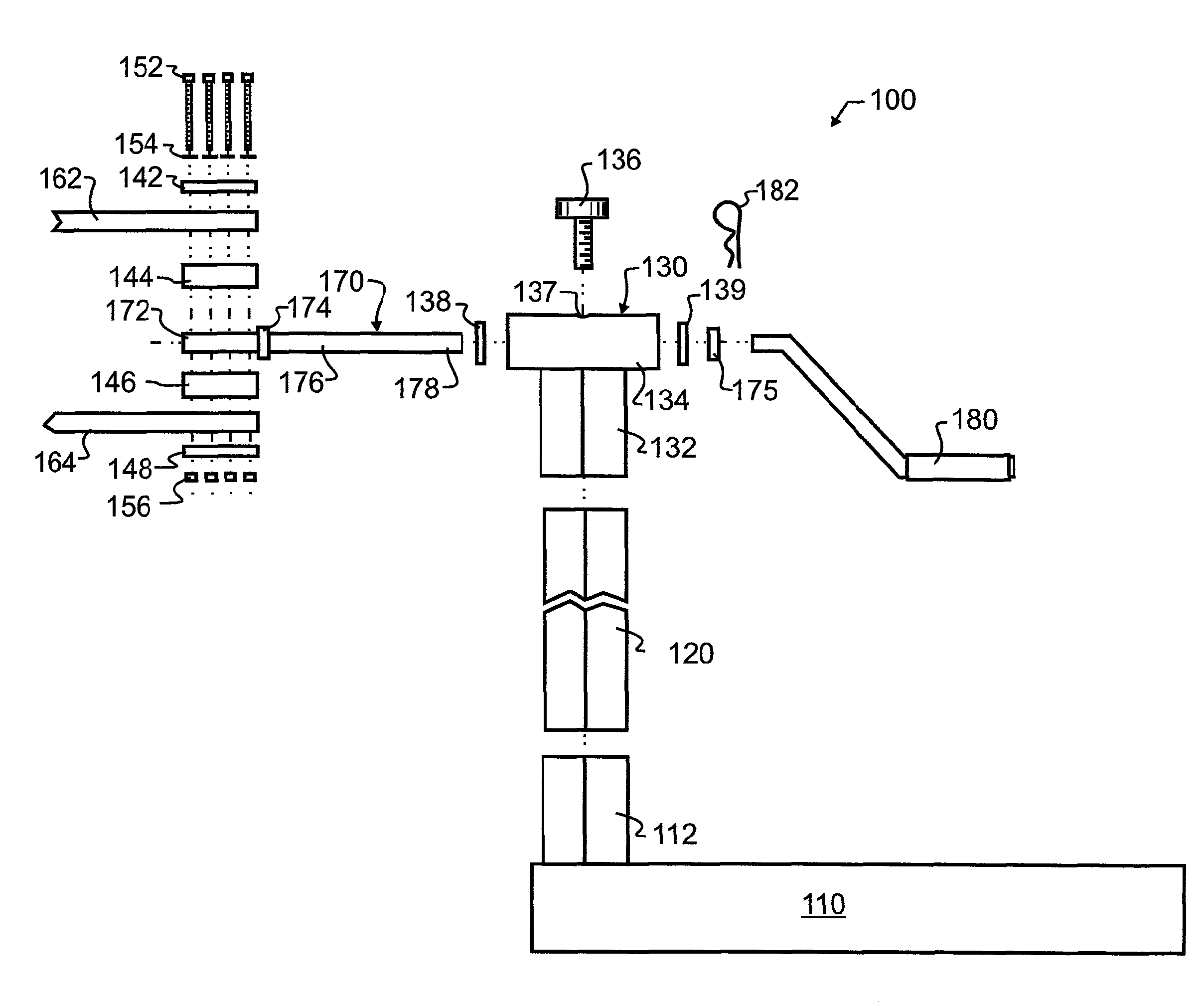
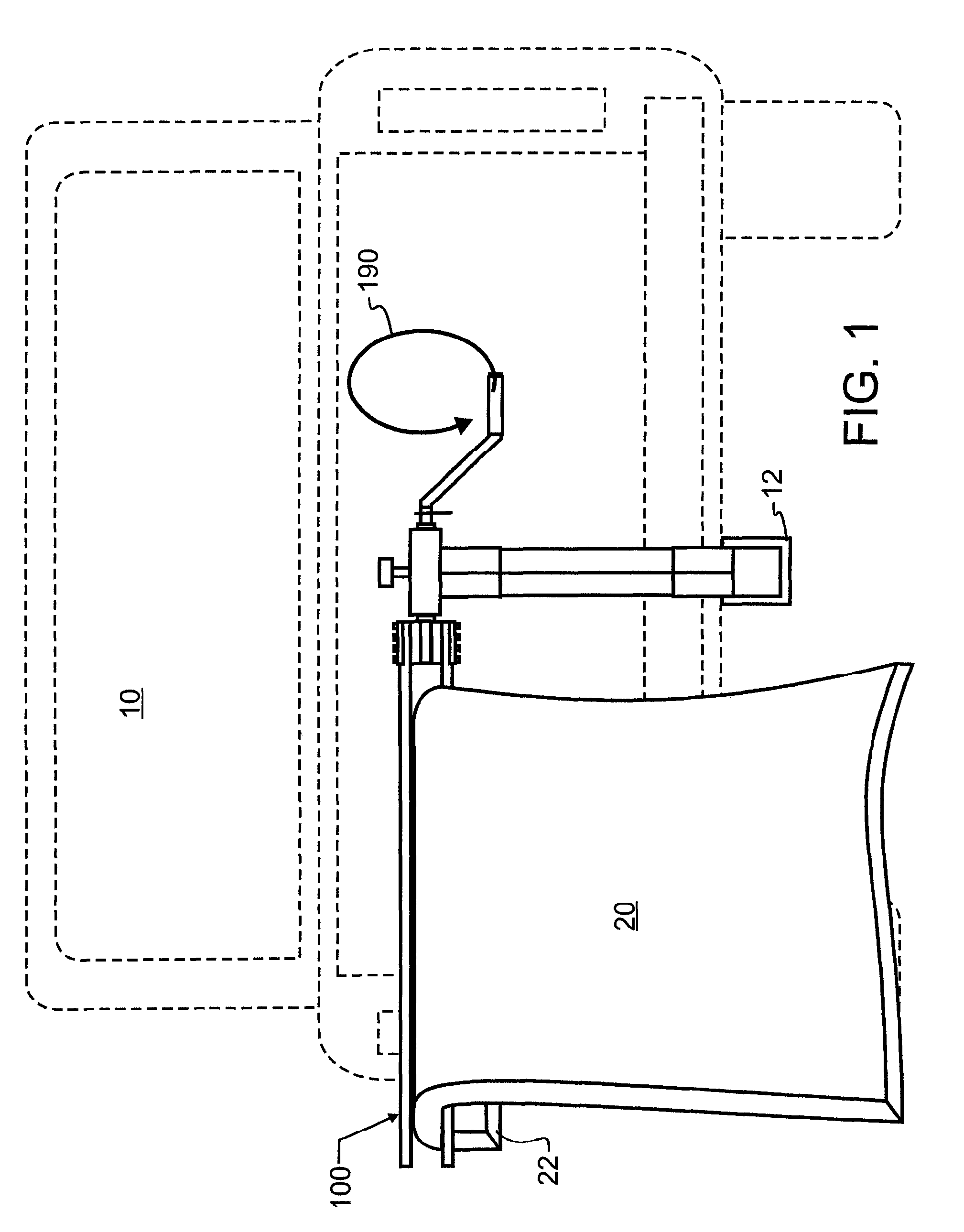
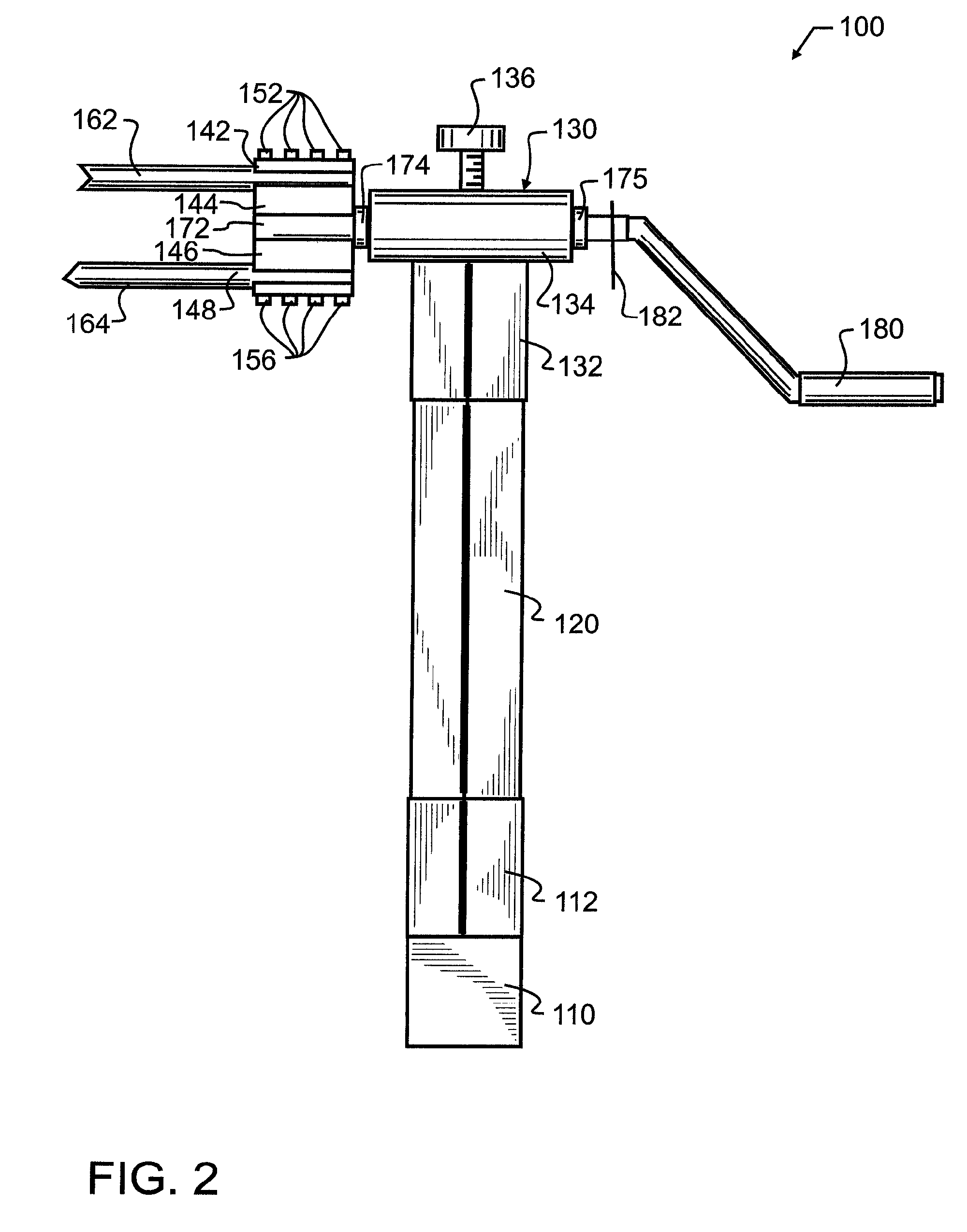
[0022]In one preferred embodiment of the invention illustrated in FIG. 1, the invention is in combination, a land vehicle 10 having a trailer hitch receiver 12, a transportable insulated blanket roller 100 supported upon land vehicle 10 by insertion within trailer hitch receiver 12, and an insulated blanket 20. This preferred combination best illustrates both the mobility of the present invention, and the ease by which benefit may be garnered. As may be apparent, to use transportable insulated blanket roller 100, an insulated blanket 20 is passed so that a leading edge 22 thereof passes between material tubes 162, 164. Only a small leading edge 22 is required, preferably sufficient to ensure that material tubes 162, 164 will capture insulated blanket 20 when handle 180 is rotated in the direction illustrated by arrow 190. Handle 180 will be rotated until insulated blanket 20 is entirely wound about material tubes 162, 164. A band of flaccid material such as a strap, cord, cinch stra...


PUM


Abstract

A transportable insulated blanket roller has a support, and a riser coupled to and extending vertically from the support. A bearing support is coupled to the riser, and has an insulated blanket retaining rod passing through the bearing support. The rod has a bifurcation defining first and second insulated blanket holding rods that are operative to receive an insulated blanket therebetween. A crank produces a rotary motion in the retaining rod, in turn winding the blanket onto the blanket holding rods. The transportable insulated blanket roller is combined with a land vehicle having a trailer hitch receiver or comparable coupling or support, and an insulated blanket. A method of efficiently using the transportable insulated blanket roller at a construction site is also presented, including using the bifurcated roller to roll an unrolled insulated blanket, and then sliding the insulated blanket off of the bifurcated roller.

Description

BACKGROUND OF THE INVENTION[0001]1. Field of the Invention[0002]This invention pertains generally to the handling of web-type materials in the building and construction industry, and more particularly to a roller designed to be supported upon a vehicle hitch receiver and configured to roll thermal insulation blankets such as are commonly used in colder weather to protect freshly poured concrete and for ground thawing applications, and which may also be used to roll other web building and construction materials that present similar challenges in rolling and storing.[0003]2. Description of the Related Art[0004]During construction of a building, pouring a concrete pad or surface, masonry work, landscaping, excavation, and in other construction projects, there are occasions that may arise in which a roll or web of material will be unwound or otherwise extended to a full longitudinal dimension that may be much greater than either width or thickness of the material. Such is the case when ...

Claims


Application Information

Patent Timeline
Patent Type & Authority Patents(United States)
IPC IPC(8): B65H75/30
CPCB65H54/585
Inventor PIEPGRAS, DOUGLAS D.
Owner PIEPGRAS DOUGLAS D
Why Eureka
Try Eureka