Ag-Bi-base alloy sputtering target, and method for producing the same

a technology of bi-base alloy and sputtering target, which is applied in the field of agbi-base alloy sputtering target and the same, can solve the problems of sputtering target having a multitude of crystal defects, currently available ag films may encounter deterioration, and ag pure films obtained, and achieve the effect of suppressing the remarkable lowering of the yield of bi content in films

Active Publication Date: 2010-08-03
KOBE STEEL LTD +1
View PDF11 Cites 23 Cited by
  • Summary
  • Abstract
  • Description
  • Claims
  • Application Information

AI Technical Summary

Benefits of technology

[0010]In view of the above, it is an object of the present invention to provide a Ag—Bi-base alloy sputtering target capable of suppressing remarkable lowering of the yield of the Bi content in films (=Bi content in the film / Bi content in the sputtering target), a method for manufacturing the sputtering target, and a method for producing Ag—Bi-base alloy films using the sputtering target.

Problems solved by technology

Despite these superior properties, the currently available Ag films may encounter deterioration resulting from oxidation, corrosion, cohesion, peeling-off, or other factor in the case where applied products of the Ag films are placed in an environment of use for a long term.
For instance, pure Ag films obtained by sputtering of the conventional sputtering target have a multitude of crystal defects such as vacancy, dislocation, and grain boundary.
Ag atoms may likely to easily migrate into these crystal defects.
For example, if the pure Ag films are stored under a condition of high temperature and high humidity, Ag atoms may likely to migrate and cohere (condense) at the defective locations, with the result that the surface roughness may be raised and oversized growth of crystal grains may appear.
Further, a material damage such as cracking is found in a process of producing sputtering targets made of the Ag—Bi-base alloy comprising the steps of: melting Ag with Bi to produce ingots, and hot-working the ingots of Ag—Bi-base alloy.
It is conceived that such a damage occurs because of low workability of the Ag—Bi-base alloy ingots.

Method used


Image

  • Ag-Bi-base alloy sputtering target, and method for producing the same
  • Ag-Bi-base alloy sputtering target, and method for producing the same
  • Ag-Bi-base alloy sputtering target, and method for producing the same

Examples


example 1

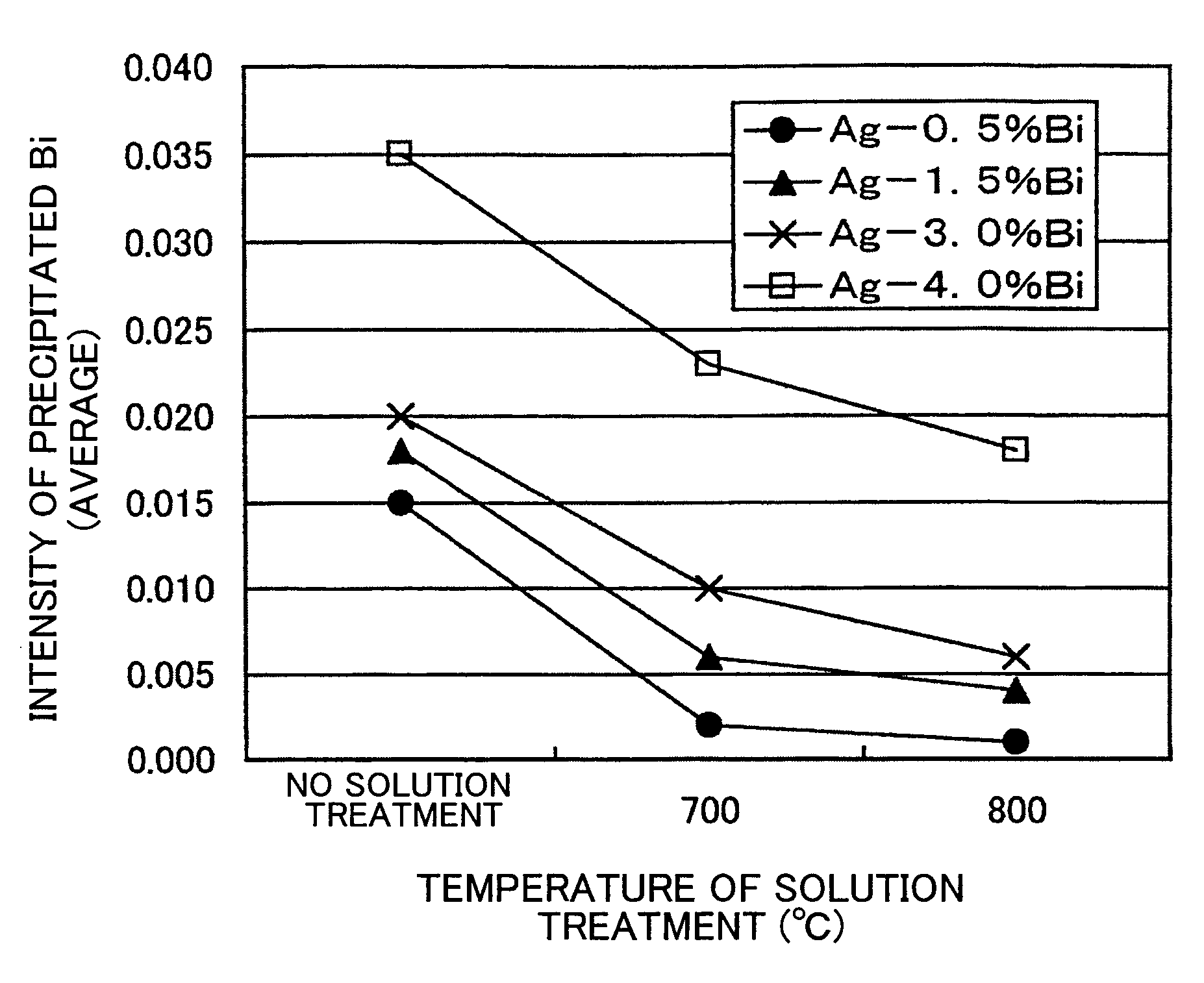
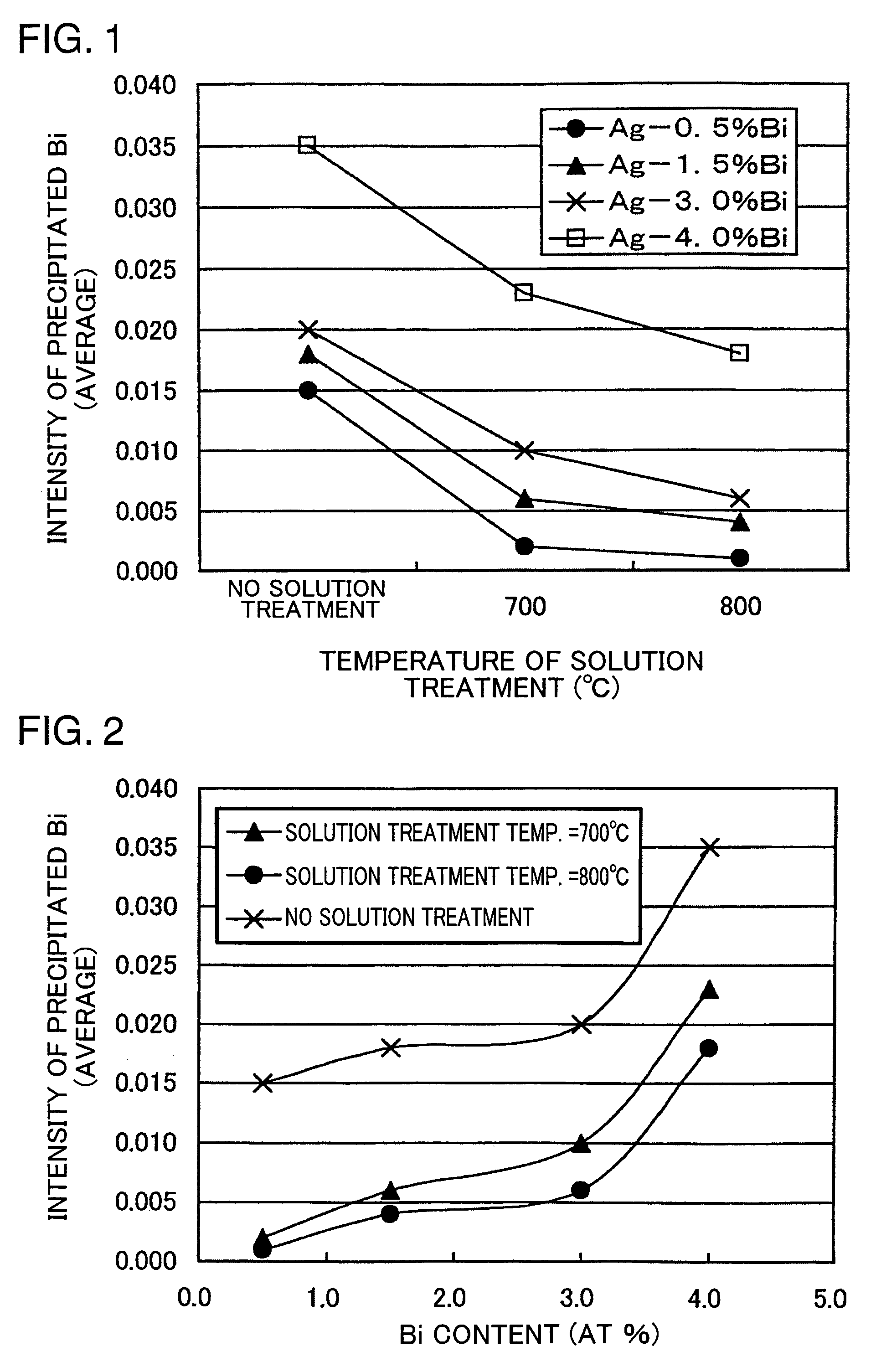
[0084]Ag and Bi whose compositions had been adjusted were inductively melted under Ar gas atmosphere, and produced were four different kinds of Ag—Bi alloy ingots each having a different Bi content, namely, Ag with Bi of 0.5 at %, Ag with Bi of 1.5 at %, Ag with Bi of 3.0 at %, and Ag with Bi of 4.0 at %. Three different kinds of treatments were performed with respect to each of the four Ag—Bi alloy ingots: the first treatment was no solution treatment; the second treatment was a solution treatment of temperature: 700(° C.)—time: 10(hr)—cooling rate: 5° C. / min; and the third treatment was a solution treatment of temperature: 800(° C.)—time: 10(hr)—cooling rate: 5° C. / min.

[0085]After either one of the three treatments was implemented, these ingots were subjected to hot working at a hot work initiate temperature of 700° C., and rolling reduction [={(plate thickness before hot rolling)−(plate thickness after hot rolling)} / (plate thickness before hot rolling)] of 50%. Thus, hot rolled p...

example 2

[0089]Ag and Bi whose compositions had been adjusted were inductively melted under Ar gas atmosphere, and produced were five different kinds of Ag—Bi alloy ingots each having a different Bi content, namely, Ag with Bi of 0.5 at %, Ag with Bi of 1.0 at %, Ag with Bi of 1.5 at %, Ag with Bi of 3.0 at %, and Ag with Bi of 4.0 at % by casting the materials into metal plates with use of a mold. Two different kinds of treatments were performed with respect to each of the five Ag—Bi alloy ingots: one was no solution treatment; and the other was a solution treatment of temperature: 700(° C.)—time: 4(hr)—cooling rate: 5° C. / min. After either one of the treatments was implemented, these ingots were subjected to hot rolling at a hot roll initiate temperature of 700° C., and rolling reduction of 50%, followed by cold rolling (rolling reduction: 50%) and heat treatment (temperature: 600° C., time: 1.5 hr).

[0090]Ag—Bi alloy sputtering targets (diameter: 101.6 mm, thickness: 5 mm) were obtained by...

example 3

[0097]Ingots were produced in a similar manner as producing the ingot made of the Ag—Bi alloy with Bi content of 1.5 at % in Example 1, and hot rolled plates were obtained by subjecting the ingots to hot working at a hot work initiate temperature of 650° C. and rolling reduction of 70% except that the solution treatment were differentiated from each other in the samples. After the hot rolled plates were subjected to cold rolling (rolling reduction: 50%) and heat treatment (temperature: 600° C., time: 1.5 hr), sputtering targets (diameter: 101.6 mm; thickness: 5 mm), and a certain number of test chips of 20 mm (length)×20 mm (width)×5 mm (thickness) necessary for implementing the experiments were obtained by cutting or shaving the plates.

[0098]Evaluation results of Example 3 are shown in Table 3.

[0099]

TABLE 3Sum of arearatiosAverageof 3rd to 6thcrystalSolution treatmentIntensityintensitiesgrain sizeconditionsof precipitated(distributionafterOversizedCoolingBiofsolutiongrowthSampleTem...


PUM

PropertyMeasurementUnit
crystal grain sizeaaaaaaaaaa
temperatureaaaaaaaaaa
melting pointaaaaaaaaaa

Abstract

The sputtering target made of a Ag—Bi-base alloy contains Bi in solid solution with Ag. The sputtering target has an intensity of precipitated Bi of 0.01 at %−1 or less, as calculated by the following mathematical expression (1) based on analysis results of X-ray diffraction, and / or a sum of area ratios of predetermined intensities (third to sixth intensities in 8 intensities) of 89% or more, wherein the area ratios are obtained by calculating a planar distribution of characteristic X-ray intensities of Bi according to X-ray microanalysis: intensity of precipitated Bi=[IBi(102) / IAg(111)+IAg(200)+IAg(220)+IAg(311))] / [Bi]. Remarkable lowering of the yield of Bi content in resultant films can be suppressed by using the sputtering target.

Description

BACKGROUND OF THE INVENTION[0001]1. Field of the Invention[0002]The present invention relates to Ag—Bi-base alloy sputtering targets useful in forming Ag—Bi-base alloy films by sputtering, a method for manufacturing the sputtering targets, and a method for producing the Ag—Bi-base alloy films using the sputtering targets.[0003]2. Description of the Related Art[0004]Ag-base films (hereinafter, simply called as “Ag films”) made of pure Ag or Ag alloy are superior in optical properties such as high reflectance and high transmittance, and low extinction coefficient, superior in thermal properties such as thermal conductivity, superior in electrical properties such as low electrical resistivity, and are superior in surface fineness. Owing to these properties, the Ag films are widely used as reflective films, semi-transparent reflective films, and heat diffusion films for optical information recording media, reflective electrode films or interconnection films for flat panel displays, Low-...

Claims


Application Information

Patent Timeline
Patent Type & Authority Patents(United States)
IPC IPC(8): C22C5/06C22F1/14B32B3/02C22C5/00C22C12/00C22F1/00C23C14/06C23C14/14C23C14/34G11B7/258G11B7/2585G11B7/259G11B7/2595G11B7/26H01L21/285
CPCC22C5/06C23C14/3414C23C14/34C22F1/14
Inventor TAKAGI, KATSUTOSHINAKAI, JUNICHITAUCHI, YUUKISATO, TOSHIKIMATSUZAKI, HITOSHIFUJII, HIDEO
Owner KOBE STEEL LTD
Why Eureka
Try Eureka