Electron beam irradiation method, electron beam irradiation apparatus, and electron beam irradiation apparatus for open-mouthed container

a technology of electron beams and electron beams, which is applied in the direction of beam/ray deflecting arrangements, meat processing devices, packaging goods, etc., can solve the problems of difficult to make electron beams hit, difficult to maintain the uniformity of irradiation, and insufficient uniformity of electron beams emitted to the whole area of the object, etc., to reduce the chance of dust adhering

Inactive Publication Date: 2010-08-03
JAPAN AE POWER SYST
View PDF22 Cites 13 Cited by
  • Summary
  • Abstract
  • Description
  • Claims
  • Application Information

AI Technical Summary

Benefits of technology

[0016]The present invention has an object to provide a method and an apparatus for irradiation with electron beams, which can reduce energy loss of the electron beams even when low-energy electron beams are used, and also provide an electron beam irradiation apparatus capable of continuous irradiation with electron beams while reducing energy loss of electron beams.
[0070]Furthermore, if the electron beam irradiation apparatus is configured according to the present invention, open-mouthed containers are rotatingly transported in upright position just as in the preceding and succeeding process lines, the transport device for open-mouthed containers is structured to rotate, so that the transport device is prevented from being subjected to unreasonable excessive force, is worn very little and can be used for a very long time, reducing chances of dust adhering to the open-mouthed containers, so that this apparatus is suitably applied to the production line for beverage, for example.

Problems solved by technology

However, control to maintain the uniformity of irradiation is very hard to implement because of the high speed with which electrons are emitted, and those technologies of the above-mentioned patent document are not sufficient in terms of uniformity of electron beams emitted to the whole area of the object.
When an object is, for example, a three-dimensional object having a complicated shape or a sheet-form material, even if the electrons are deflected, it is difficult to make electron beams hit the side of an object opposite to the side facing the irradiating part of the electron beam irradiation means because of a large Larmor radius and fringing fields.
It has been proposed to irradiate the opposite side of the object with secondary electrons reflected from the object and the reflector plate, but since the secondary electrons suffer large energy loss due to space distance, it is still difficult to maintain specified doses of radiation and achieve uniform irradiation.
Moreover, electron beams emitted from the electron beam irradiation apparatus of this kind collide with a surrounding gas as the ambient atmosphere and hit the structural part of the apparatus other than the object, the electron beams lose much of their energy.
For this reason, it becomes more difficult to irradiate the object with electron beams uniformly.
When objects are transported continuously on a continuous production line, the above problems make it difficult to irradiate transported objects with low-energy electron beams uniformly and with high energy efficiency.

Method used


Image

  • Electron beam irradiation method, electron beam irradiation apparatus, and electron beam irradiation apparatus for open-mouthed container
  • Electron beam irradiation method, electron beam irradiation apparatus, and electron beam irradiation apparatus for open-mouthed container
  • Electron beam irradiation method, electron beam irradiation apparatus, and electron beam irradiation apparatus for open-mouthed container

Examples


first embodiment

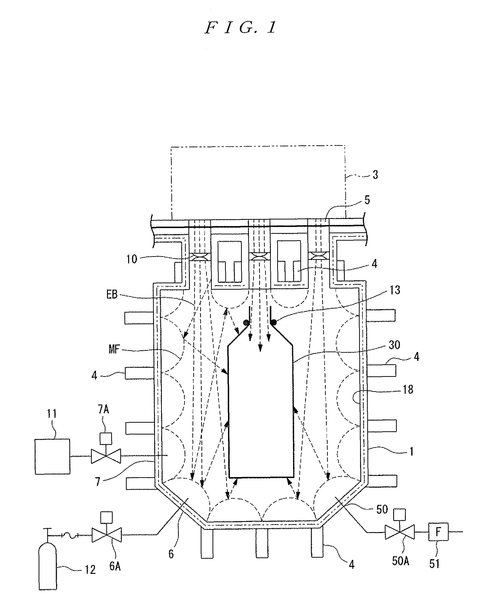
[0177]FIG. 1 is a schematic configuration diagram showing an electron beam irradiation apparatus according to the present invention. Note that in FIG. 1, a nearly cylindrical irradiation chamber, which forms the main body of the electron beam irradiation apparatus, is shown in a cross section including the axis line.

[0178]As shown in FIG. 1, the electron beam irradiation apparatus includes a chamber 1 for irradiation with electron beams EB. This chamber 1 is a tight-sealed vessel of a pressure-resistant structure in a sufficient size to accommodate a beverage container, and formed in a nearly cylindrical shape with the axis line extending in the longitudinal direction. The chamber 1 is made of steel or stainless steel, and is covered, on its surfaces, with an X-ray shielding material, though this is not shown.

[0179]The chamber 1 is provided on its top with an electron beam irradiation means 3 for emitting electron beams towards electron beam irradiation area in the chamber. The elec...

second embodiment

[0191]An electron beam irradiation apparatus according to the present invention will be described as follows.

[0192]FIG. 3 is a schematic configuration diagram showing the electron beam irradiation apparatus according to a second embodiment of the present invention. Note that those configurations in the second embodiment which are identical with those of the first embodiment are designated by the same reference numerals and their descriptions are omitted where necessary.

[0193]In the second embodiment, a difference from the first embodiment is that the electron beams EB that have plunged into the chamber 1 are allowed to move disorderly, which is made possible by the distances and the directions of the arrangement of the permanent magnets as the magnetic field generators.

[0194]More specifically, in this electron beam irradiation apparatus, as shown in FIG. 3, a turntable 14 as the magnetic field barrier forming means is further added to the bottom of the chamber 1, which is a notable ...

third embodiment

[0196]An electron beam irradiation apparatus according to the present invention will be described in the following.

[0197]FIGS. 4A and 4B are schematic configuration diagrams showing an electron beam irradiation apparatus according to a third embodiment of the present invention. FIG. 4A is a front view and FIG. 4B is a plan view, each showing the irradiation chamber in cross section. Those configurations which are identical with those in the above-described embodiments are designated by the same numerals and their descriptions are omitted where necessary.

[0198]The third embodiment has the magnetic field barrier forming means of the first embodiment located within the chamber in a way to enclose the electron beam irradiation area, and this embodiment is particularly an example of an apparatus structure suitable for irradiation of a beverage container 30 with electron beams on a batch type production line.

[0199]This electron beam irradiation apparatus includes a box-shaped chamber 21 e...


PUM

PropertyMeasurementUnit
specific gravityaaaaaaaaaa
pressureaaaaaaaaaa
heightaaaaaaaaaa

Abstract

There are provided an electron beam application method and an electron beam application device capable of uniformly applying electron beams to an object even if the electron beams have a low energy. For this, electron beams (EB) are applied to a beverage container (30) (object) within a magnetic barrier (MF) formed by combining a plurality of magnetic fields generated in an electron beam application region.

Description

FIELD OF THE INVENTION[0001]The present invention relates to an electron beam irradiation method and an electron beam irradiation apparatus for emitting electron beams to an object, more particularly to an electron beam irradiation method and an electron beam irradiation apparatus for emitting electron beams suitable for sterilizing objects, such as food and drink, water, pharmaceutical products, Chinese medicines, cosmetics, feeding stuffs, fertilizer, or to packaging material for those objects, and more particularly to an electron beam irradiation apparatus suitable for sterilizing the interior and exterior surfaces of plastic open-mouthed containers.BACKGROUND OF THE ART[0002]The conventional electron beam irradiation methods and apparatuses of this kind have been generally configured to irradiate the objects with high-energy electron beams by utilizing the penetration power. The conventional electron beam irradiation methods and apparatuses of high energy type had a problem that...

Claims


Application Information

Patent Timeline
Patent Type & Authority Patents(United States)
IPC IPC(8): G21K1/08H01J3/26H01J3/14H01J49/42
CPCA23L3/26A61L2/087G21K5/00B65B55/027B65B55/08A61L2202/122A61L2202/23A61L2202/21A61L2/08
Inventor EGUCHI, SHIROHASHIMOTO, ISAOSATO, SHIGEKATSUKOIDE, HIDENOBUHASHIMOTO, NOBUYUKISUZUKI, TAKAYUKIGOZAKI, SATORUHIKOSAKA, TOMOYUKIOKAMOTO, YUKIOFUJITA, HIROYUKI
Owner JAPAN AE POWER SYST
Why Eureka
Try Eureka