
Radiative decay engineering

a technology of radioactive decay and fluorescence, which is applied in the field of compositions and methods for increasing and detecting the fluorescence of a molecule, can solve the problems of affecting the biological activity of the biomolecule, affecting the detection effect of the molecule of interest, and reducing so as to improve increase the intrinsic fluorescence of the biomolecule, and enhance the intrinsic emission of electromagnetic radiation

Inactive Publication Date: 2010-08-17
UNIV OF MARYLAND BALTIMORE
View PDF24 Cites 10 Cited by
  • Summary
  • Abstract
  • Description
  • Claims
  • Application Information

AI Technical Summary

Benefits of technology

"The present invention relates to a method for enhancing the fluorescence of a biomolecule by positioning a metal particle and the biomolecule at a distance from each other. This enhancement can be achieved by increasing the intrinsic fluorescence of the biomolecule or by using extrinsic fluorophores that are positioned close to the metal particle. The distance between the metal particle and the biomolecule can be increased by manipulating the exciting electromagnetic radiation. The invention also provides a method for selectively enhancing a region of electromagnetic emission in a sample. The technical effects of the invention include increased sensitivity and reduced background fluorescence, as well as lower costs and faster detection."

Problems solved by technology

Nonetheless, the intrinsic fluorescence from DNA is of little practical usefulness because of the low quantum yields of 10−4 to 10−5 (Vigny et al.
Detection of the molecule of interest is generally limited by the properties of the fluorophore used.
In some cases, labeling a biomolecule with an extrinsic fluorophore can alter the biological activity of the biomolecule potentially creating experimental artifacts.
Problems with current fluorescent techniques stem in part from the low fluorescent intensities of commonly used fluorophores.
Additionally, background fluorescence can be significant when using low wavelength excitation radiation required by some fluorophores or when large quantities of fluorophore are required.
As a result, these DNA sequencing techniques have several disadvantages including high costs resulting from the high cost of the lasers used to excite the fluorescent markers which typically emit in the visible region of light spectrum and the high noise to signal ratio due to the background interferences by biomolecules.

Method used


Image

  • Radiative decay engineering
  • Radiative decay engineering
  • Radiative decay engineering

Examples


example 1

Procedure for Making Metal Nanoparticle Films

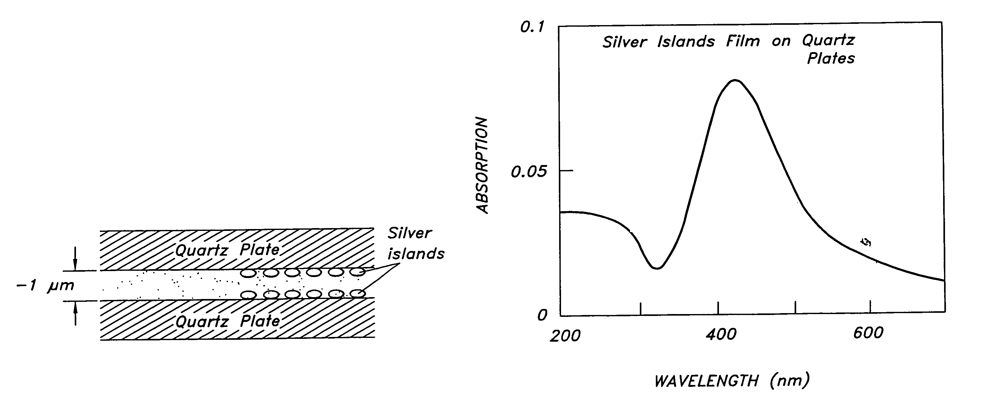
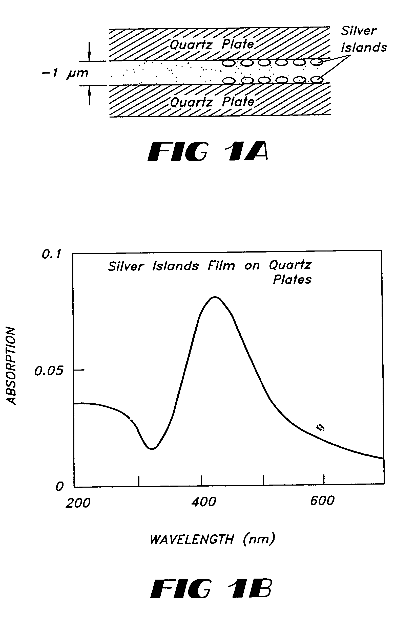
[0128]Metal particles or metal particle films are known and can be produced using known methods. The following example uses silver but it will be appreciated that any metal can be used, preferably noble metals. Chemicals used to generate silver particles, silver nitrate (99+%), sodium hydroxide (pellets, 97%), ammonium hydroxide (NH3 content 28-39%), and D-glucose (99.5%) were purchased from commercial suppliers and used without further purification. All procedures were performed using distilled water which was further purified by Millipore filtration. Silver islands were formed on quartz microscope slides. Quartz provided UV transmission and less autofluorescence. The quartz slides used to deposit silver particles were soaked in a 10:1 (v / v) mixture of H2SO4 (95-98%) and H2O2 (30%) overnight before the deposition. They were washed with water and air-dried prior to use.

[0129]Silver deposition was carried out in a clean 30-ml beaker equipp...

example 2

Effects of Silver Island Films on Emission Spectra and Lifetimes

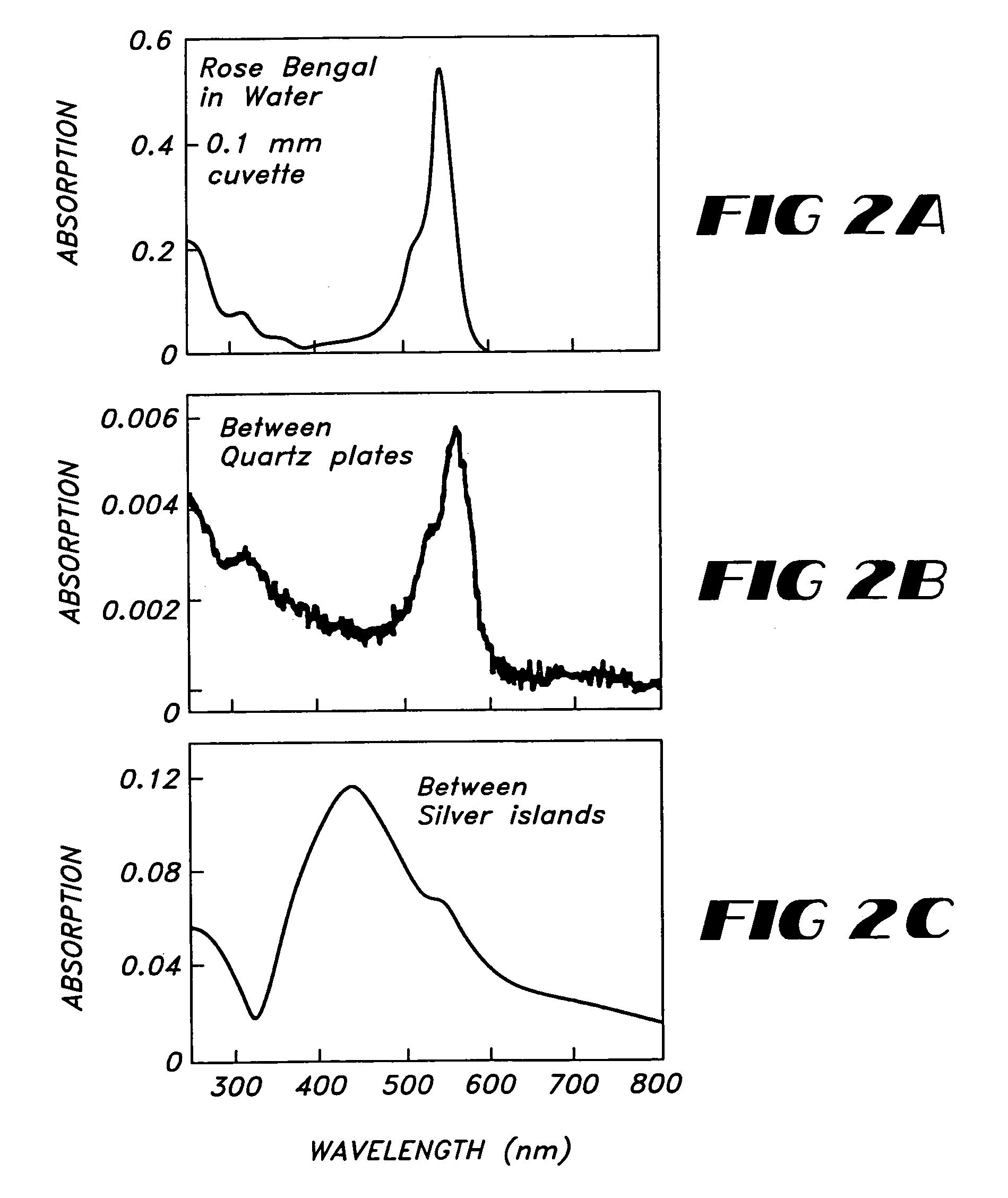
[0135]As an initial experiment, the emission spectra of rhodamine B (RhB) and rose bengal (RB) between uncoated quartz plates (Q) or silver island films (S) were examined. These two fluorophores were selected because of their similar absorption and emission spectra but different quantum yields of 0.48 and 0.02 for RhB and RB, respectively. In the case of RhB the intensities are similar in the absence and presence of these silver islands (FIG. 3A). There may be a small decrease in the RhB intensity due to the silver islands, which may be due to the quenching effects of metals at short distances.

[0136]Contrasting results were obtained for rose bengal (FIG. 3B). In this case the intensity increased about 5-fold in the presence of silver islands. It is important to recognize that the increased intensity observed for RB represents an underestimation of the quantum yield of RB near the silver islands. This is because only a s...

example 3

Spectral Shifts in the Presence of Silver Islands

[0144]FIGS. 10A and 10B show the emission spectra of two solvent sensitive fluorophores between quartz plates (Q) and silver islands (S). In both cases blue shifts in the emission, which are consistent with a decreased lifetime of fluorophores near the islands were observed. Because fluorophores within 50 Å of the metal are likely to be quenched, it is unlikely that the blue shifts seen in FIG. 10A and FIG. 10B are due to fluorophores bound to the silver islands. Binding of fluorophores to the uncoated quartz surface is also unlikely because uncoated quartz is present for both emission spectra.


PUM

PropertyMeasurementUnit
wavelengthsaaaaaaaaaa
excitation wavelengthaaaaaaaaaa

Abstract

Compositions and methods for increasing the fluorescence intensity of molecules are provided. In particular, compositions and methods directed to increasing the intrinsic fluorescence of biomolecules and low quantum yield fluorophores are described. The intrinsic fluorescence of biomolecules is increased by positioning a metal particle and a biomolecule at a distance apart sufficient to increase the radiative decay rate of the biomolecule. Methods for the identification of nucleic acids are also provided. The compositions and methods can also be used to increase the emission of any fluorophore, such as the extrinsic probes used to label biomolecules.

Description

CROSS REFERENCE TO RELATED APPLICATIONS[0001]This application is a Divisional of U.S. application Ser. No. 10 / 073,625, filed Feb. 11, 2002; which claims benefit of priority under 35 U.S.C. §119(e) to U.S. provisional application No. 60 / 268,326 entitled “RADIATIVE DECAY ENGINEERING” filed on Feb. 14, 2001, the disclosure of each of which is hereby incorporated by reference in their entireties.STATEMENT REGARDING FEDERALLY SPONSORED RESEARCH[0002]The work leading to this invention was supported in part by the U.S. Government under grant number RR-08119 awarded by the NIH National Center for Research Resources; Therefore, the U.S. Government may have certain rights in this invention.BACKGROUND OF THE INVENTION[0003]1. Field of the Invention[0004]The present invention is directed to compositions and methods for increasing, and detecting the fluorescence of a molecule, in particular, compositions and methods for increasing the intrinsic fluorescence of a biomolecule. This invention also ...

Claims


Application Information

Patent Timeline
Patent Type & Authority Patents(United States)
IPC IPC(8): C12Q1/68G01N33/53G01N21/76C07K14/00C07H21/02C07H21/04C12M1/00C12Q1/6818C12Q1/682G01N21/78G01N33/542G01N33/553G01N33/58G01N37/00
CPCC12Q1/6818C12Q1/682Y10S436/805Y10T436/143333C12Q2563/143C12Q2563/149C12Q2563/107
Inventor LAKOWICZ, JOSEPH R.
Owner UNIV OF MARYLAND BALTIMORE
Learn More