
Apparatus and method using synchronized breathing to treat tissue subject to respiratory motion

Active Publication Date: 2010-08-17
WISCONSIN ALUMNI RES FOUND
View PDF18 Cites 76 Cited by
  • Summary
  • Abstract
  • Description
  • Claims
  • Application Information

AI Technical Summary

Benefits of technology

[0011]The present invention provides a general method of using IMRT equipment to treat tissue having periodic motion allowing the patient to breathe continuously, and providing treatment times and dose distributions comparable to those of treating motionless tumors.
[0016]Thus it is another object of the invention to provide a simple method of generating a model of an organ that reflects changes in the organ with periodic motion.
[0018]It is thus another object of the invention to provide a simple method of incorporating information about organ motion and warping into conventional treatment planning systems.
[0024]It is another object of the invention to provide a means for allowing a patient to synchronize his or her breathing to a standard pattern.
[0030]It is another object of the invention then to provide a simple and intuitive display for the purpose of allowing the patient to match his or her breathing to the standard pattern.

Problems solved by technology

The treatment of targets having respiratory motion such as non-small cell lung cancer presents a problem for treatment planning for IMRT equipment because the tumor moves with movement of the lungs over the course of the treatment.
Such an approach increases the length of time required for the radiation therapy and, by implicitly allowing some tumor motion during treatment, cannot achieve the highest dose conformity possible with IMRT.
Particularly for patients with lung disease, such breath-hold techniques can be difficult.

Method used


Image

  • Apparatus and method using synchronized breathing to treat tissue subject to respiratory motion
  • Apparatus and method using synchronized breathing to treat tissue subject to respiratory motion
  • Apparatus and method using synchronized breathing to treat tissue subject to respiratory motion

Examples


first embodiment

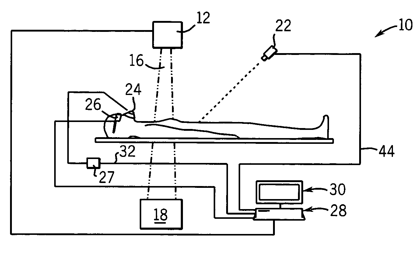
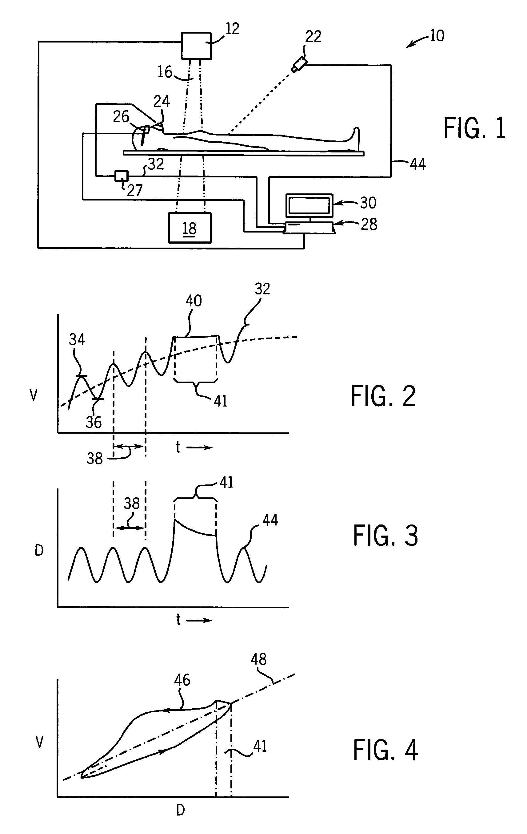
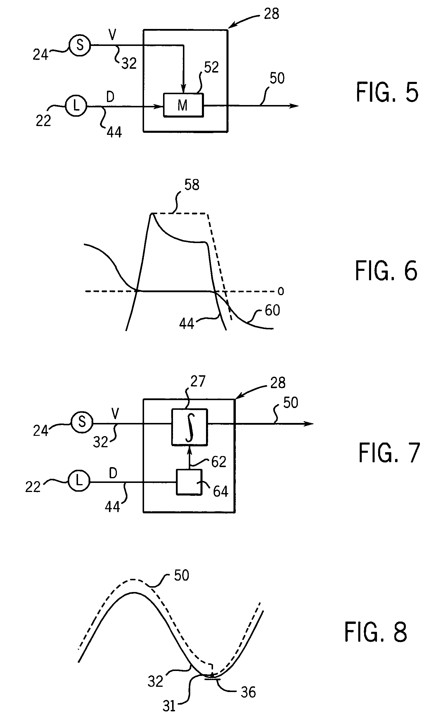
[0064]In a first embodiment, the model 52 receives the lung volume signal 32 and the chest displacement signal 44 to deduce the slope of the slope line 48. The chest displacement signal 44 is then scaled by the slope to translate the chest displacement into units of lung volume, but without drift as the corrected respiration signal 50.

[0065]Referring now to FIG. 6, when breath-hold measurements are required, the model 52 may provide for breath-hold-detection to hold corrected respiration signal 50 constant when a breath-hold is detected. In one embodiment, the breath-hold detection may monitor the laser chest displacement signal 44. Breath-hold can be detected from the shape of the chest displacement signal 44 in which the derivative of this signal changes abruptly at the beginning and ending of breath-hold or from spirometer signal 60 in which the flow reading is zero during breath-hold. When a breath-hold is detected, the corrected respiration signal 50 is held to a constant value...

second embodiment

[0066]In a second embodiment, the correlation curve 46 may be captured as a lookup table fitted to a nonlinear equation and used to map arguments of the chest displacement signal 44 to values of lung volume according to the function captured by the correlation curve 46. By detecting an instantaneous change in the input of the chest displacement signal 44 and using the direction of this change to apply the chest displacement signal to either the upper or lower portion of the correlation curve 46, respectively, a model 52 that accommodates hysteresis can be obtained. The use of correlation curve 46 to convert the chest displacement signal 44 into values of lung volume effectively eliminates the decay artifact in the chest displacement signal 44 because the flat portion of the correlation curve 46 during breath-hold period 41 holds lung volume output constant during the breath-hold period 41. The correlation curve 46 may be an average of a number of breathing periods 38 after baseline ...


PUM


Abstract

Radiation treatment of the lung or surrounding tissue during continuous breathing is made possible by preparing a treatment plan linked to motion phase and then synchronizing the plan to motion phase as the patient follows a regular breathing schedule.

Description

CROSS-REFERENCE TO RELATED APPLICATIONS[0001]This application claims the benefit of U.S. Provisional application 60 / 478,584 filed Jun. 13, 2003 which is hereby incorporated by reference.STATEMENT REGARDING FEDERALLY SPONSORED RESEARCH OR DEVELOPMENT[0002]This invention was made with United States government support awarded by the following agencies: NIH CA88960. The United States has certain rights in this invention.BACKGROUND OF THE INVENTION[0003]The present invention relates to radiation therapy equipment and in particular to a method and apparatus of using intensity modulated radiation therapy equipment for the treatment of targets subject to respiratory motion such as tumors related to lung cancer and liver cancer.[0004]Intensity modulated radiation therapy (IMRT) systems treat a tumor with converging “beamlets” of radiation (being separately controllable portions of a radiation beam) of different intensities. The overlapping pattern of the beamlets allows the delivered radiati...

Claims


Application Information

Patent Timeline
IPC IPC(8): A61B5/05A61B5/087A61B5/113A61B6/00A61N5/10
CPCA61B5/1135A61B6/541A61N5/1048A61B5/087A61N5/1037A61N5/1042A61N5/1064
Inventor ZHANG, TIEZHIPALIWAL, BHUDATT R.
Owner WISCONSIN ALUMNI RES FOUND
Learn More