

Suction system with high efficiency suction control valve
- Summary
- Abstract
- Description
- Claims
- Application Information
AI Technical Summary
Benefits of technology
Problems solved by technology
Method used
Image


Examples
Embodiment Construction
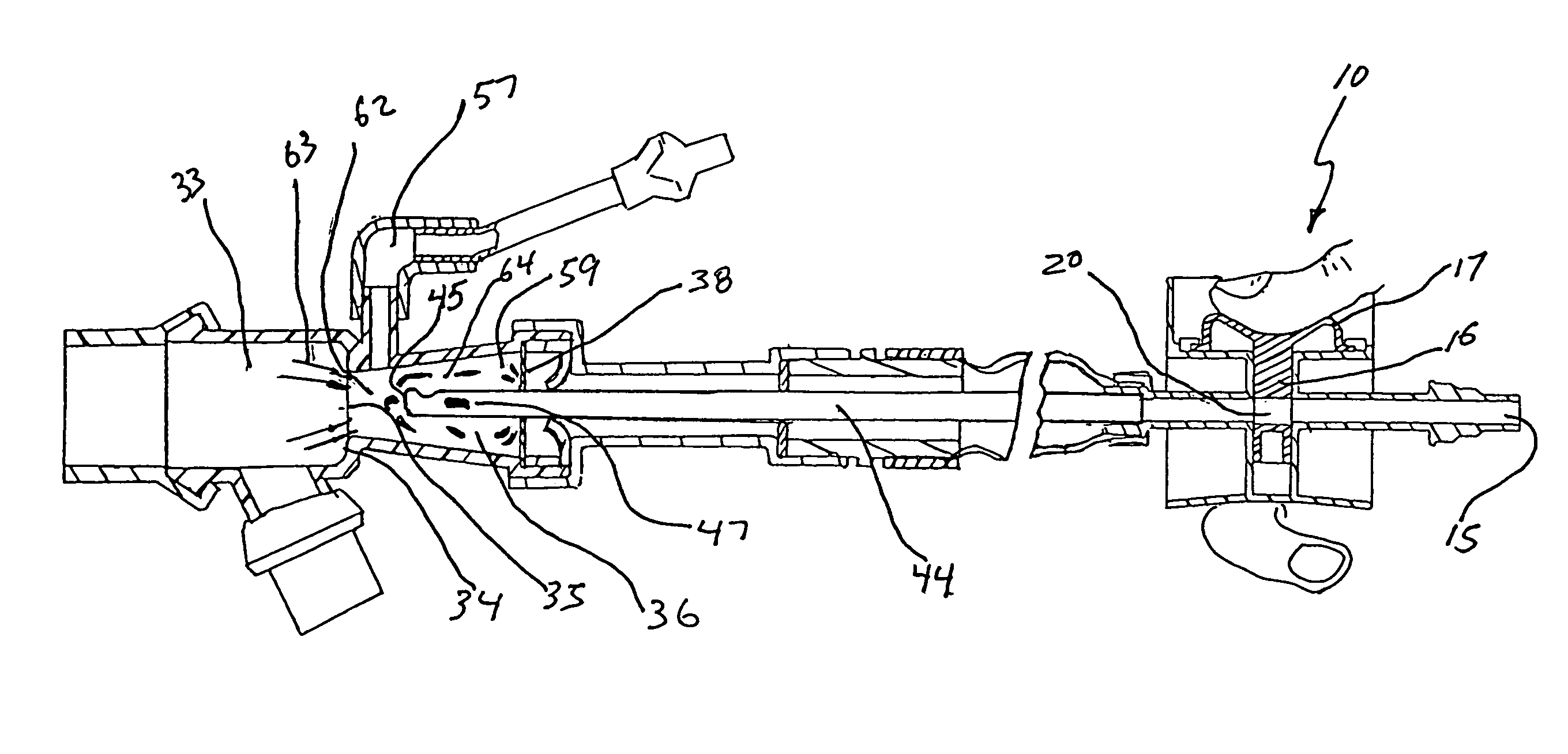
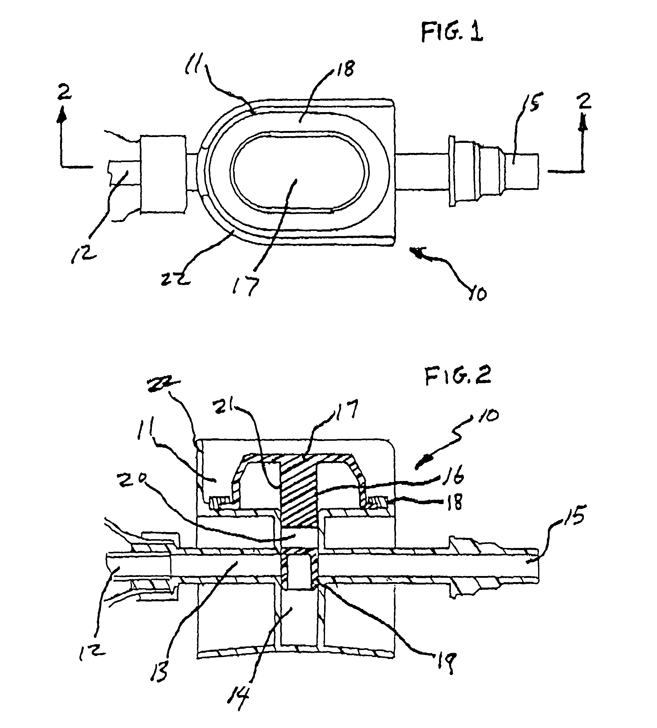
[0037]FIGS. 1 and 2 clearly show the suction control valve 10 in its normally positioned closed non-suction applied mode. The valve 10 has a one-piece rigid injection molded housing 11 made from ABS or PVC plastic which can solvent cement to any catheter 12. The housing 11 has a main first central linear straight through fluid and airflow passageway 13 that is in straight-line communication with the catheter 12. The transversing passageway 13 is transverse to second passageway 14. The passageway 13 extends past the second passageway 14 rearward to built-in suction connector 15 which permits direct connection to any source of regulated vacuum or suction via suction tubing. Inserted into second transversing passageway 14 is synthetic rubber molded plunger 16 that is typically circular in cross section and also has a top resiliently manually depressively activated button actuator portion 17 that is generally oval in shape. A sealing ring 18 hermetically seals plunger 16 and actuator po...
PUM
 Abstract
Description
Claims
Application Information