Method and system for calibrating frequencies-amplitude and phase mismatch in a receiver
a frequency-amplitude and phase mismatch technology, applied in the field of receivers and mobile radio terminals, can solve problems such as problems, and achieve the effect of widening the frequency band and high-accuracy image rejection
- Summary
- Abstract
- Description
- Claims
- Application Information
AI Technical Summary
Benefits of technology
Problems solved by technology
Method used
Image
Examples
first embodiment
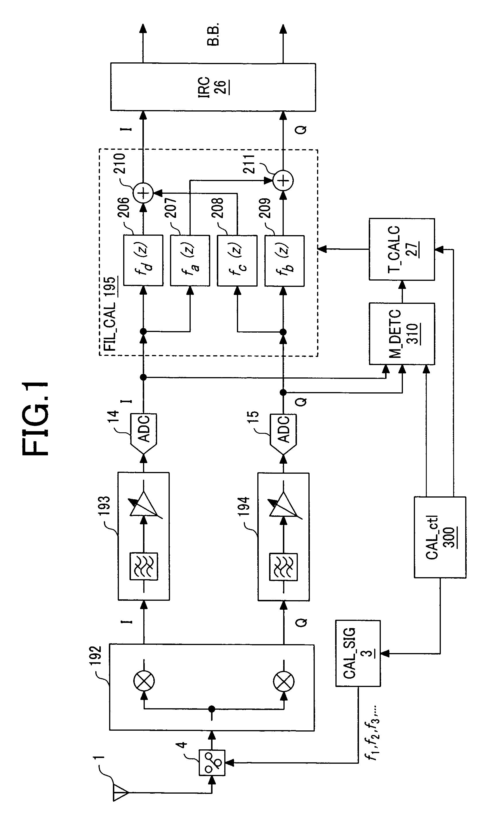
[0061]A first embodiment of the present invention will be explained with reference to FIG. 1 to FIG. 8.
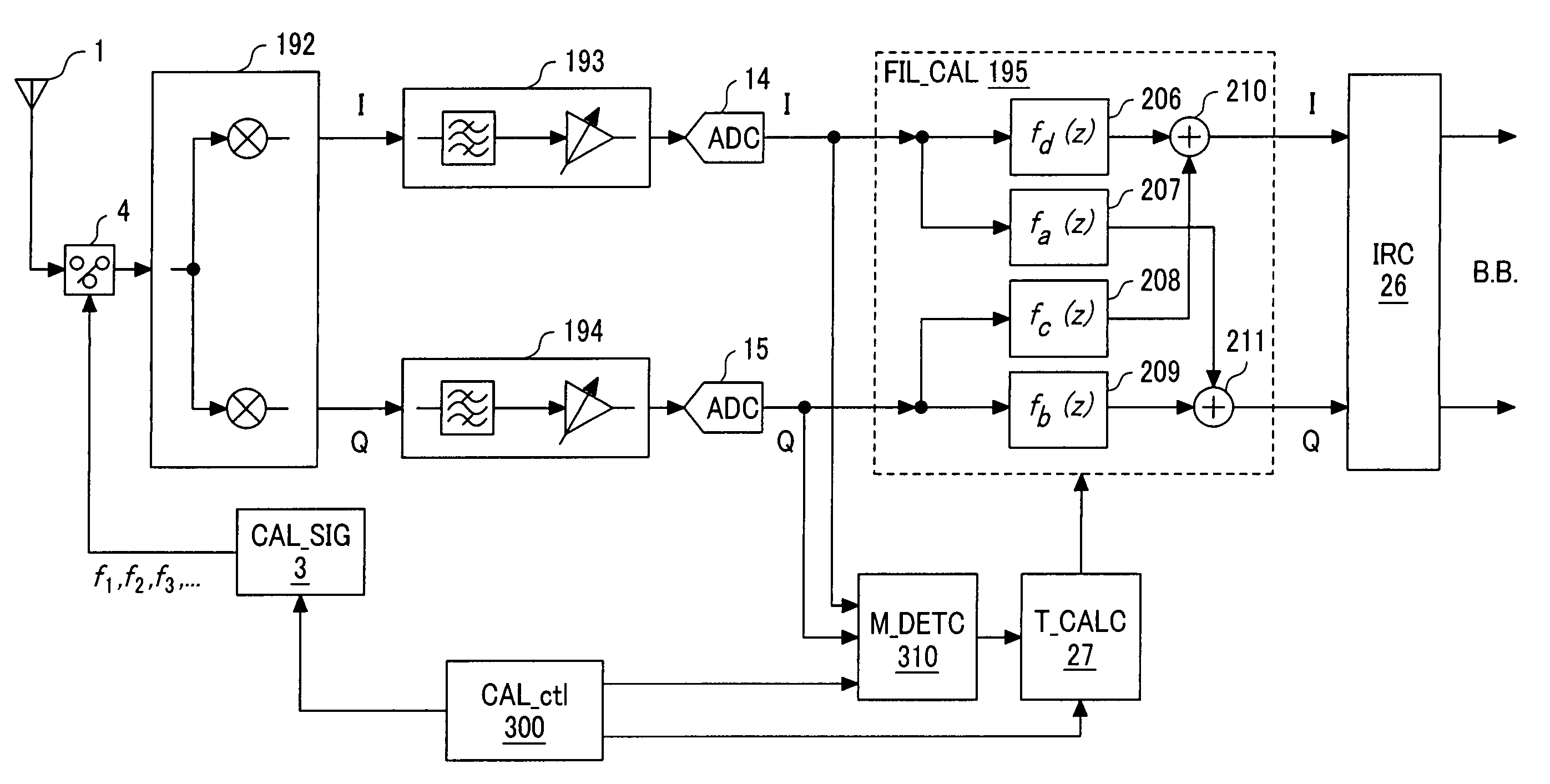
[0062]First, FIG. 1 illustrates an example of structure of a receiver as the first embodiment of the present invention. A low IF receiver illustrated in FIG. 1 comprises an antenna 1, a calibration signal source 3, a switch 4, a quadrature mixer 192, an I component signal path 193, a Q component signal path 194, analog / digital converters (hereinafter referred to as “ADCs” (analog to digital converters) 14, 15, a filter mismatch calibrating circuit (FIL_CAL) 195, an image rejecting circuit (IRC) 26, a tap coefficient calculating circuit (T_CALC) 27, a calibration control circuit (CAL_ctl) 300, and a filter mismatch detecting circuit (M_DETC) 310.
[0063]This embodiment is characterized in comprising a filter mismatch calibrating unit including the calibration signal source 3, switch 4, tap coefficient calculating circuit (T_CALC) 27, filter mismatch calibrating circuit (FIL_CAL) 195, ...
second embodiment
[0112]The second embodiment of the present invention will be described with reference to FIG. 9 to FIGS. 19A and 19B. This embodiment corresponds to a receiver employing the low IF system.
[0113]First, FIG. 9 illustrates a circuit structure of the low IF receiver as the second embodiment of the present invention. The low IF receiver illustrated in FIG. 9 comprises an antenna 1, an LNA 2, a calibration signal source 3, switches 4, 16 to 19, 22, 23, mixers 5, 6, an analog 90° phase shifter 7, an RF synthesizer 8, band-pass filters (BPFs) 9, 10, a control circuit 11, programmable gain amplifiers 12, 13, and analog / digital converters (ADCs) 14, 15. Moreover, the receiver also comprises a filter mismatch calibrating circuit (FIL_CAL) 20, a correction coefficient calculating circuit (C_CALC) 21, a memory (MEM) 24, an amplitude / phase mismatch calibrating circuit (GP_CAL) 25, an image rejecting circuit (IRC) 26, and a tap coefficient calculating circuit (T_CALC) 27.
[0114]This embodiment is c...
third embodiment
[0186]FIG. 20 shows an example of the other structure of the calibration signal source 3 as the third of the present invention. The calibration signal source 3 shown in the figure is constituted with inclusion of a crystal-controlled oscillator 118, a harmonics generating circuit 161, inverters 123, 124, differential amplifiers 125, 126 and switches 127, 128. The reference signal generated with the crystal-controlled oscillator 118 is inputted to the harmonics generating circuit 161. The harmonics generating circuit 161 of the third embodiment is formed of a PLL (Phase Locked Loop) and a fixed frequency divider with inclusion of a phase comparator (PD) 119, a low-pass filter (LPF) 120, a ring oscillator 121, a variable frequency divider (DIV) 122, and a frequency divider 162. The phase comparator (PD) 119, LPF 120, ring oscillator 121, and variable frequency divider (DIV) 122 form a PLL. In the phase comparator (PD) 119, the frequency of reference signal is compared with the frequen...
PUM
 Abstract
Description
Claims
Application Information
 - R&D
- Intellectual Property
- Life Sciences
- Materials
- Tech Scout
- Unparalleled Data Quality
- Higher Quality Content
- 60% Fewer Hallucinations
Browse by: Latest US Patents, China's latest patents, Technical Efficacy Thesaurus, Application Domain, Technology Topic, Popular Technical Reports.
© 2025 PatSnap. All rights reserved.Legal|Privacy policy|Modern Slavery Act Transparency Statement|Sitemap|About US| Contact US: help@patsnap.com


