Methods and compositions for improved light traps

a technology of light traps and compositions, applied in the field of methods and compositions for improving light traps, can solve the problems of reducing the efficiency of light traps, and reducing so as to reduce the number of traps and reduce the effect of effective capture of arthropods in irregular shape areas

Inactive Publication Date: 2010-08-31
COHNSTAEDT WILLIAM MARTIN +1
View PDF17 Cites 37 Cited by
  • Summary
  • Abstract
  • Description
  • Claims
  • Application Information

AI Technical Summary

Benefits of technology

[0034]Another advantage of the invention is that the size and shape of the attraction zone may be adjusted to meet certain conditions or target certain arthropods. For example, a trap may incorporate 8 variable angle LEDs, each of which has an effective 50 degree window to provide for 360 degree coverage in a uniform manner. (A small degree of overlap between LED ranges is desired to provide effective coverage.) Alternatively, the same trap may be adjusted so that 4 LEDs have an effective 90 degree window to, again, provide uniform 360 degree coverage. The remaining 4 LEDs may emit a different wavelength(s) of light or a narrower effective degree window. For example, the remaining 4 LEDs may have an effective 30 degree window so that they emit a brighter (higher intensity) light. This configuration allows light to be broadcast farther on the cardinal points, which would increase the field of collection along those points while maintaining the local area of capture. It also allows the number of traps needed to effectively capture arthropods in an irregularly shaped area to be reduced.
[0035]For example, a barn with 4 corridors arranged in an “X” shape would need a minimum of 2 conventional traps; however, using the invention, the same barn could be equipped with a single trap located at the center of the “X” and achieve the same results. Another example is the trapping area next to a tree or house. The invention allows the shape of the zone of attraction to be adjusted to minimize illumination of the tree or structure and maximize illumination of the open area. This ability to adjust the shape of the trapping zone improves energy efficiency, which in turn, reduces labor and costs associated with trap maintenance.
[0036]The invention also includes features to reduce the possibility of damage from reverse electrical current. Reverse electrical current is second only to battery failure as the leading cause for trap problems during field collections. Insect field collection traps commonly use 6 volt batteries or battery packs to provide power. Confusing the positive and negative terminal is a common occurrence when installing traps. The Zener diode protects the LEDs from this reverse current. Zener diodes are not used in fluorescent or incandescent light traps because fluorescent and incandescent light bulbs are not ruined by reverse current. Known LED traps do not incorporate a Zener diode because the traps are not modular, interchangeable, or adaptable; and therefore, the possibility of incorrectly inserting the positive and negative terminals is remote.
[0037]The user can control certain parameters that necessitate a plurality of lighting conditions of said device that are adjustable as desired. These parameters may include bulb replacement, that allows for insect genera specific platforms, particular trapping habitats, and different insect targets. Typical trapping habitats include caves, domestic structures, forests, and fields.
[0038]This invention encompasses systems and methods to maximize the capture of a plurality of arthropod species, preferably targeted species, by using light emitting diode (LED) technology to mimic the light frequency sensitivity(ies) of arthropod species and act as an energy efficient visual attractant to them. Advantageously, the invention provides for greater flexibility because the colors or wavelengths, viewing angles, and intensities of any or all of the LEDs may altered to suit different environments, conditions, and targeted arthropods.
[0039]The invention includes mimicking LEDs that have narrow light spectra and can be used to attract or repel insects based on the insects' innate responses to visual stimulants, including both attraction as positive phototaxis and repulsion as negative phototaxis. The energy efficient LED technology is used for monitoring, controlling, trapping, and studying arthropods and the diseases they transmit.B. Components of Lighting Systems

Problems solved by technology

Additionally, insects cause enormous agricultural damage worldwide either directly or indirectly through disease transmission.
In general, ultraviolet (UV) light traps attract more insects than similar white light traps, but power consumption is much greater for UV traps and is often a limiting factor.
Further, the collection of non-target insects and arthropods in either type of trap can complicate results and analyses.
Adequate public health surveillance is often impossible because of the high costs and logistical problems associated with using current CDC-traps or comparable light traps.
Other limitations of known capture traps include an inability to readily adjust to different conditions or environments, irregularly shaped areas, and to target specific insects or arthropods.
Importantly, none of these examples provide for or teach a means of selective trapping that is crucial for reliable surveillance and pest control without damage to non-target, beneficial species.
Further, neither Weiss nor any other known patent or application disclose or teach using light emitted from LEDs without a reflector or light mixer of some type.
Using a reflector reduces the field of insect capture by creating blind spots behind the reflectors.
Presently, the art does not provide or teach traps that can be adjusted or programmed to selectively target a species or group of arthropods in one set of circumstances and then be adjusted to selectively target a different species or group of arthropods in another set of circumstances.

Method used


Image

  • Methods and compositions for improved light traps
  • Methods and compositions for improved light traps
  • Methods and compositions for improved light traps

Examples


example 1

Basic Lighting Systems

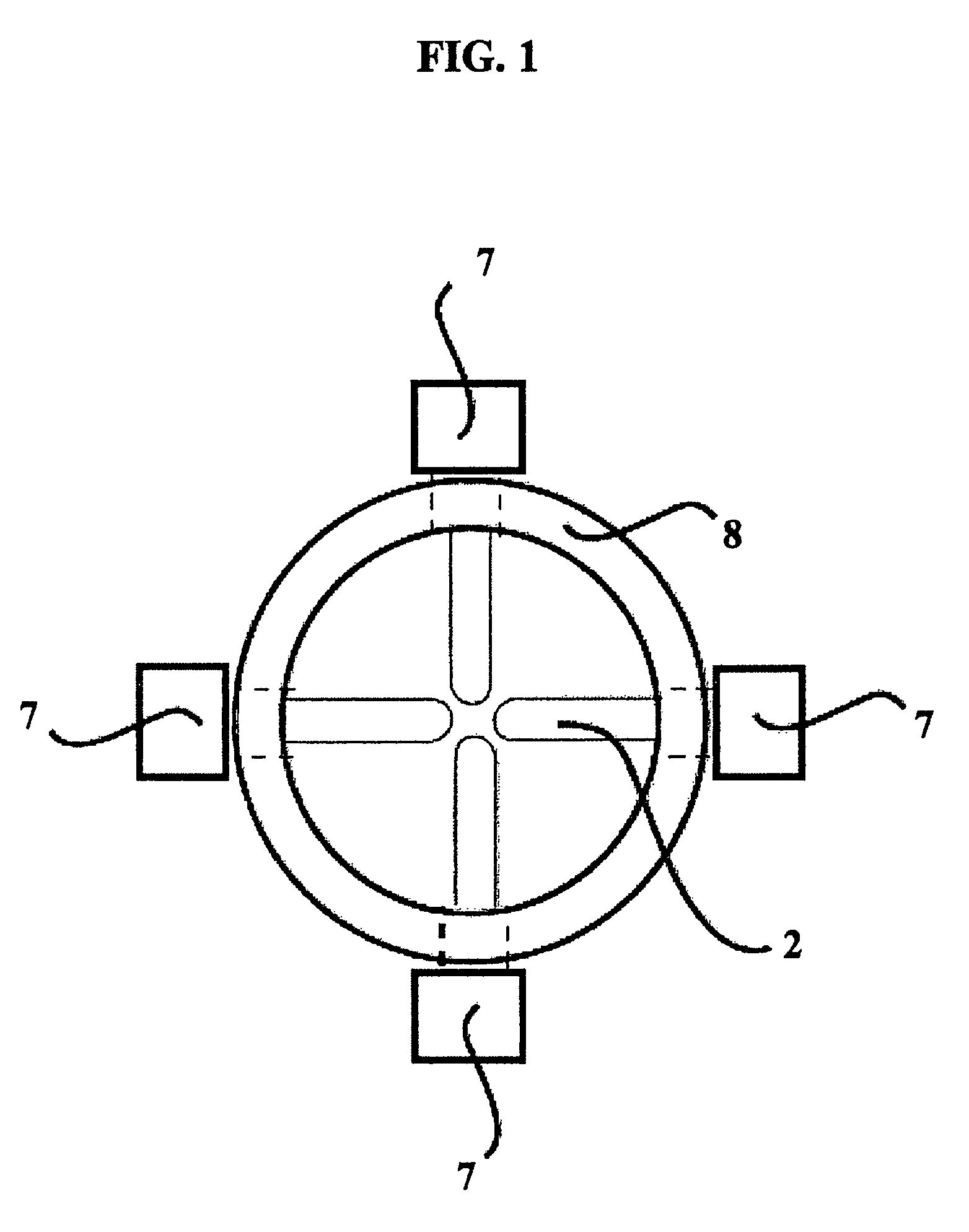
[0077]A lighting system was made to replace existing incandescent bulbs in Center for Disease Control (CDC) light traps for disease and insect surveillance. The system was made using from four Toyoda-Gosei UV LEDs wired in parallel with 30 ohm resistors to regulate the current in an electrical circuit and attached to a supporting member, UV resistant tubing.

[0078]The LEDs face the four cardinal points and are held in place by UV resistant tubing. The tubing allows the four LEDs to be removed and replaced as a whole by changing the entire unit or lighting platform. The tubing and individual resistors allows for additional wavelengths or LEDs to simply be added to the existing tubing or alternative units can be used. Additionally, the LEDs are protected by an added 6 volt Zener diode placed within the electrical circuit and a 200 mA fuse to protect the other electronics in the trap.

example 2

Maximizing Brightness to Attract Terrestrial Pests to an Irregularly Shaped Area

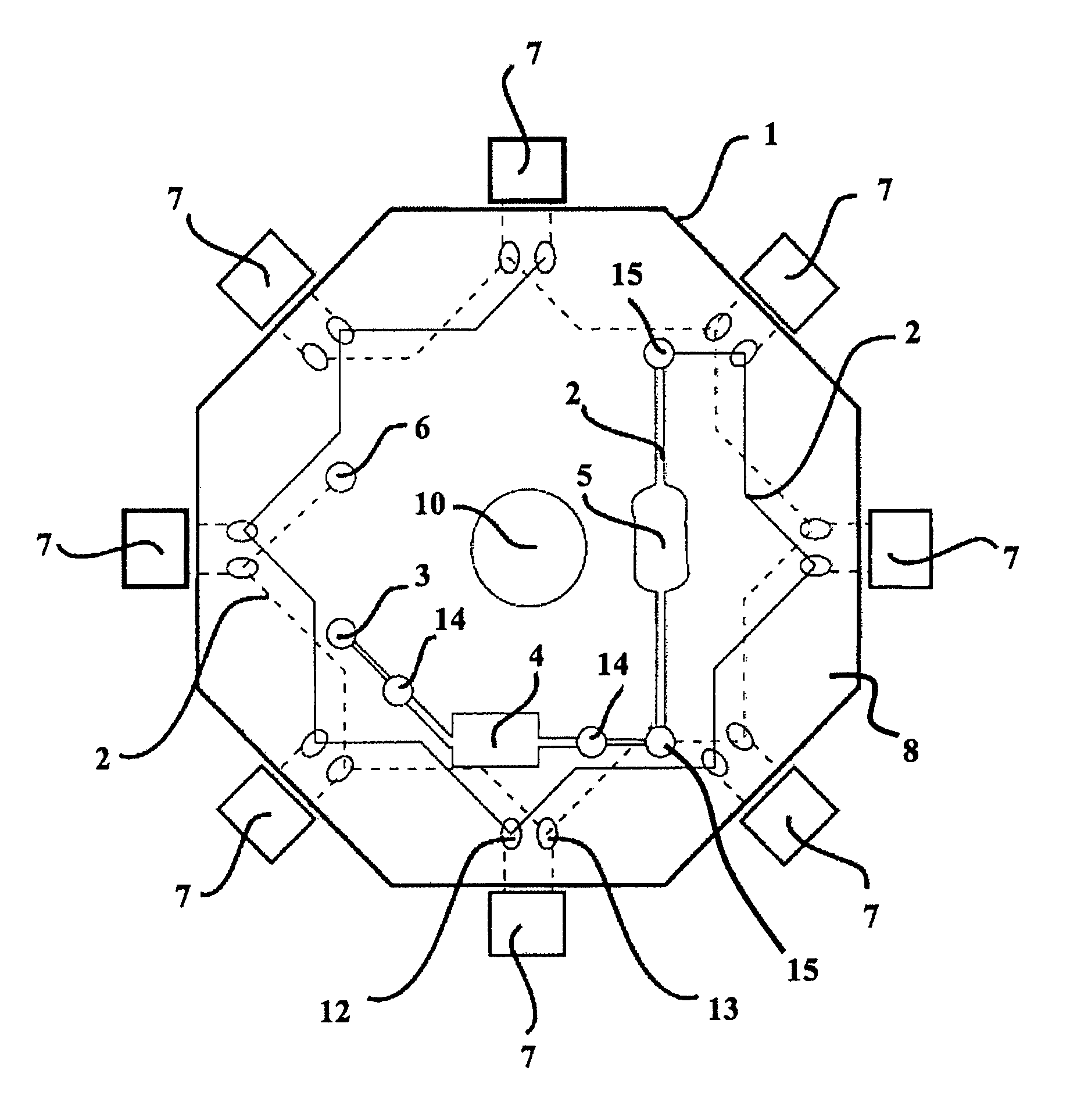
[0079]Grain beetles have a photopigment with maximum stimulation between 350-370 nm. A decagonal lighting system is designed that contains five 350 nm LEDs with a viewing angle of 60 degrees and five 370 nm LEDs with a viewing angle of 30 degrees. The LEDs are alternated within the ten slots, one on each side of the polygon. The 350 nm light, therefore, illuminates a conical area completely surrounding the trap but only projects a few meters (<20 m) while the narrower angled 370 nm bulbs project a greater distance (at least 50 m) to attract beetles. The combination of lights, frequencies, and angles maximizes the capture area, attraction of the beetles of interest, and the brightness of the trap. The terrestrial beetles that inhabit grain silos will be attracted to the lights and be removed from the grain preventing spoilage and insect damage.

[0080]Optionally, additional lighting platforms may be added t...

example 3

A Cylindrical Replacement Lighting System

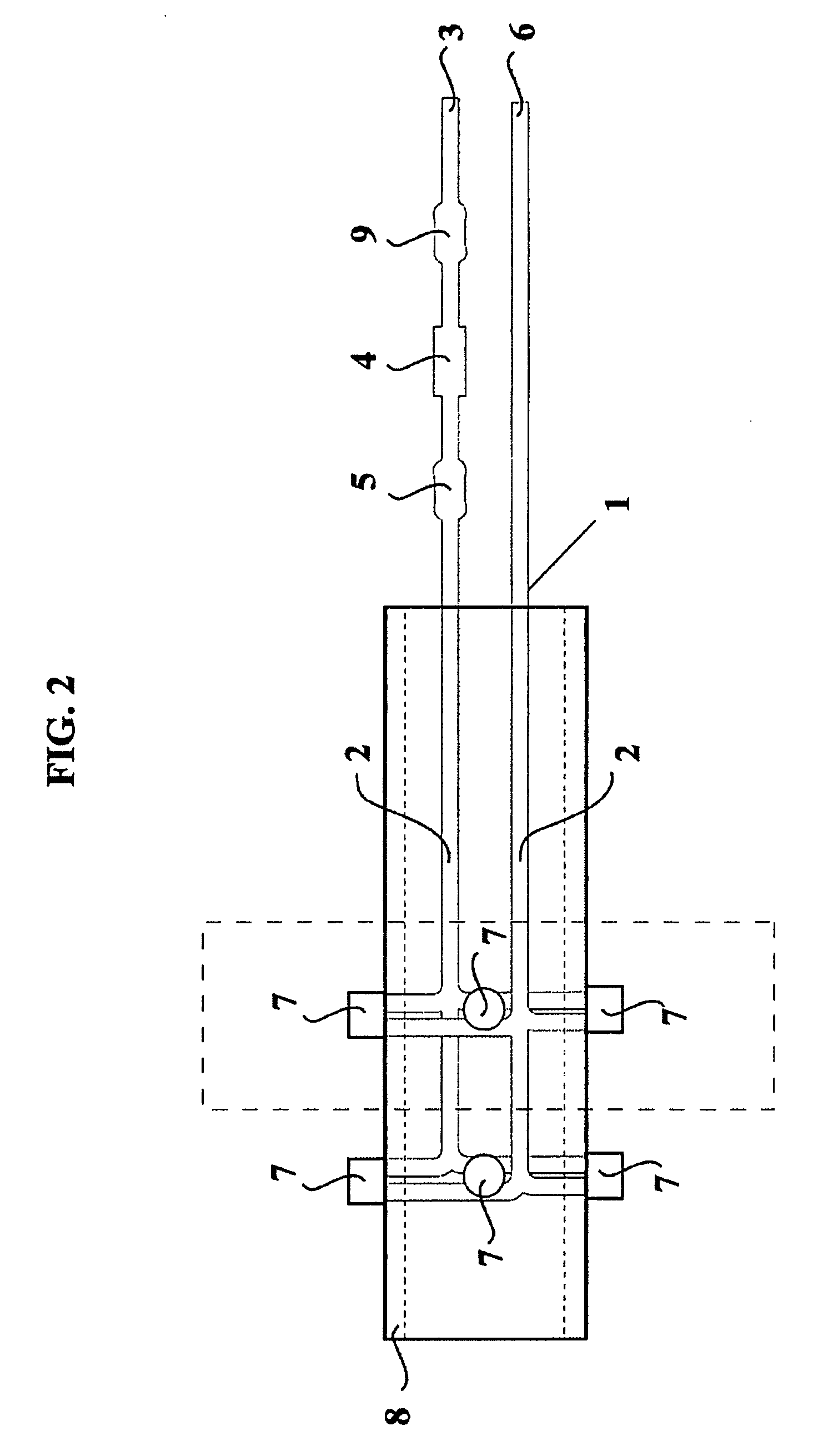
[0081]Sand flies are known to be attracted to flowers for sugar meals. Four ultraviolet 370 nm LEDs with a 90 degree viewing angle can be combined with six blue / green 500 nm LEDs with viewing angles of 60 degrees. This pattern simulates flowers on plants and is much brighter than natural flowers to the insect's photo-pigments, and therefore, appears as a giant flower.

[0082]Using a cylindrical supporting member to support a lighting platform yields a structure that is similar in shape to a conventional incandescent or fluorescent tube light. The cylindrical nature of the lighting system allows it to fit within the incandescent light mount on CDC-light traps or similar conventional traps and replace the incandescent or fluorescent light. The lighting system essentially acts as a replacement bulb and is inserted into the trap in a similar manner.


PUM


Abstract

A process and device to attract a multitude of terrestrial and aerial arthropods using a plurality of light wavelengths emitted from light emitting diodes (LEDs). The selected light wavelengths increase trap capture rates by taking advantage of the insect's physiological and behavior instincts associated with vision and sensory perception. The LED wavelengths (light color) are selected to mimic the electromagnetic spectra of natural features, such as sugar and blood meal resources within the target insect's environment. Lighting platforms containing a plurality of LEDs produce the mimicking colors and can be optimally arranged in either a cylindrical fashion or on polygonal lighting chips. These two types of lighting platforms can be modified to fit existing insect traps, used in new light trap designs, or incorporated into insect traps currently lacking a lighting component.

Description

RELATED APPLICATIONS[0001]This application relates to and claims priority to U.S. Provisional Patent Application No. 60 / 585,266, which was filed Nov. 9, 2006, and to U.S. Provisional Patent Application No. 60 / 961,773, which was filed Jul. 24, 2007. Both of which are commonly owned and incorporated herein by reference in their entireties.FEDERALLY SPONSORED RESEARCH OR DEVELOPMENT[0002]Not applicable.FIELD OF THE INVENTION[0003]The present invention relates to devices, kits, and methods for the capture of terrestrial and aerial arthropods based on their propensity to move towards a specific color or color combination. More specifically, this invention provides a replaceable and adjustable lighting system that allows for increased capture rates of targeted arthropods by mimicking their natural visual attractants. The lighting system also provides improved energy efficiency and enables capture traps to be adapted to various environments, conditions, and arthropods of interest.BACKGROUN...

Claims


Application Information

Patent Timeline
Patent Type & Authority Patents(United States)
IPC IPC(8): A01M1/22
CPCA01M1/04
Inventor COHNSTAEDT, LEE WILLIAMGILLEN, JONATHAN ISAIAHCOHNSTAEDT, WILLIAM MARTIN
Owner COHNSTAEDT WILLIAM MARTIN
Why Eureka
Try Eureka