
Anisotropic conductive material

a technology of anisotropic conductivity and conductive material, which is applied in the direction of non-metal conductors, photosensitive materials, auxillary/base layers of photosensitive materials, etc., can solve the problems of not being able to disclose procedures, the difficulty of connecting circuit parts at very fine pitches, and the difficulty of connecting electrical components at ever increasing precision. achieve the effect of widening the operation window and better anisotropic conductivity

Inactive Publication Date: 2010-08-31
TEAMCHEM COMPANY
View PDF20 Cites 8 Cited by
  • Summary
  • Abstract
  • Description
  • Claims
  • Application Information

AI Technical Summary

Benefits of technology

"The present invention provides an improved polymer material for the applications of anisotropic conductive adhesives, films or sheets. The material includes a base resin system comprising an epoxy resin, a hardener and a catalyst, and a filamentary nickel powder dispersed in the base resin system. The filamentary nickel powder acts as an essential conductive component in an anisotropic conductive adhesive, film or sheet. The resulting material displays better anisotropic conductivity and can provide anisotropic conductivity even when the final adhesive film thickness is several times greater than the diameter of the conductive particle. The filamentary nickel powder is an aggregate of smaller spiked spherical particles having particle sizes ranging between 0.2-0.5 microns. The base epoxy system consists of an epoxy resin, a hardener and a catalyst. The epoxy resin reacted with acid anhydride has been found to possess superior chemical and thermal resistance. The material can provide better performance in various applications such as anisotropic conductive adhesives, films or sheets."

Problems solved by technology

Consequently, electronic product manufacturers have faced the issue of having to connect electric components at ever increasing precisions.
Although the traditional method of soldering has been proven to be fairly reliable and easy to operate, it has troubles with connecting circuit parts at very fine pitches.
The disclosed procedures are not practical.

Method used


Image

  • Anisotropic conductive material
  • Anisotropic conductive material
  • Anisotropic conductive material

Examples


Embodiment Construction

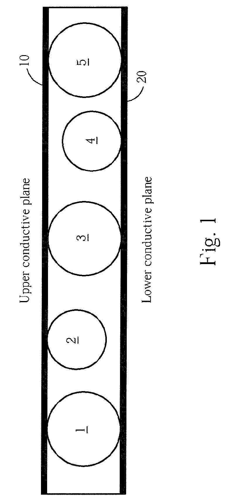
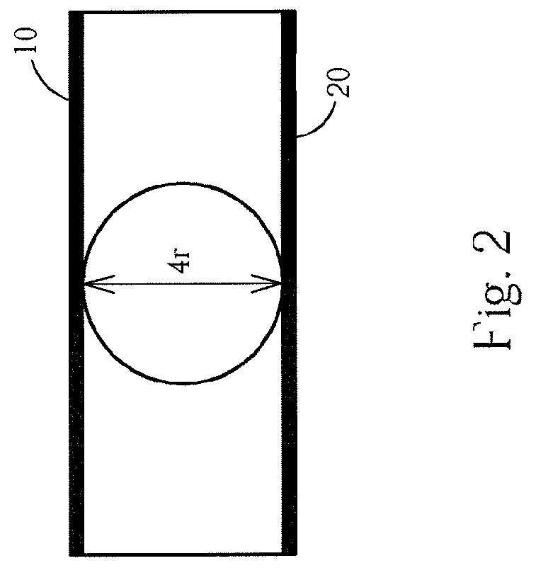
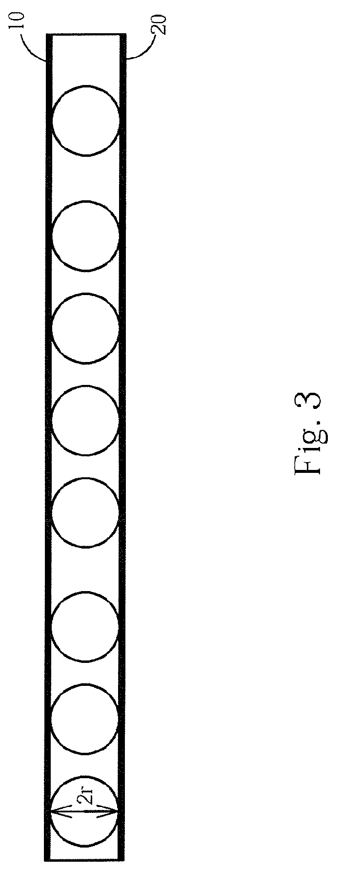
[0035]The present invention relates to an anisotropic conductive material that can be applied to bond two electronic components or two conductive surfaces / planes together. The anisotropic conductive material allows electricity to be conducted only in z-direction (or in thickness direction), but not along x- and y-directions (x- and y-directions are parallel to the substrate surfaces to be bonded together, and z-direction is perpendicular to the substrate surfaces). The aforesaid reference x-, y- and z-coordinate system and the conductive planes are demonstrated in FIG. 7. As shown in FIG. 7, the anisotropic conductive material (not explicitly shown) is filled between the conductive plane A and conductive plane B with bumps 70 therebetween.

[0036]A filamentary nickel powder dispersed in a thermosetting epoxy resin forms the basis of an anisotropic conductive material system. Various forms of the anisotropic conductive materials, such as anisotropic conductive film (ACF), anisotropic c...


PUM

PropertyMeasurementUnit
diameteraaaaaaaaaa
particle sizesaaaaaaaaaa
particle diameteraaaaaaaaaa

Abstract

Compositions consisting of a mixture of filamentary nickel powder(s) and a thermosetting epoxy resin form the basis of anisotropic conductive materials. The filamentary nickel powder has a three-dimensional chain-like network structure. When such filamentary nickel powder is dispersed in a polymer thin film, such as an epoxy resin, it exhibits anisotropic conductivity.

Description

BACKGROUND OF THE INVENTION[0001]1. Field of the Invention[0002]The present invention relates to an anisotropic conductive material. More particularly, the present invention relates to a composition of an electrical anisotropic polymer material.[0003]2. Description of the Prior Art[0004]As propelled by consumer preferences, electronic products have become smaller in size, lighter and more compact. It is also required that the electronic products are able to process more information at higher speeds. Consequently, electronic product manufacturers have faced the issue of having to connect electric components at ever increasing precisions.[0005]Although the traditional method of soldering has been proven to be fairly reliable and easy to operate, it has troubles with connecting circuit parts at very fine pitches. Different anisotropic conductive materials, such as anisotropic conductive film (ACF), anisotropic conductive adhesive (ACA) or anisotropic conductive sheet (ACS) have all fou...

Claims


Application Information

Patent Timeline
Patent Type & Authority Patents(United States)
IPC IPC(8): H01B1/00H01B1/12H01B1/02G03C1/76B32B5/16
CPCH01B1/22H05K3/323Y10T428/25Y10T428/258H05K2201/0281
Inventor YEH, SYH-TAU
Owner TEAMCHEM COMPANY
Learn More