Fluid transport in monolithic structures

a monolithic structure and fluid technology, applied in the direction of valve housings, transportation and packaging, mechanical equipment, etc., can solve the problems of increasing the overall space required for installation and use of the canister, increasing the overall space required for the canister, and weakening and failure of the welded joints between the components and at the canister joints, so as to achieve less depth and more cost-effective implementation

Active Publication Date: 2010-09-07
TALON INNOVATIONS CORP
View PDF9 Cites 8 Cited by
  • Summary
  • Abstract
  • Description
  • Claims
  • Application Information

AI Technical Summary

Benefits of technology

[0020]One skilled in the use of MSM fluidic components will appreciate that the use fluidic inserts embedded into the surface of monolithic fluidic structures represents a significant and novel method for the direct implementation of MSM fluidic components. The use of embedded fluidic inserts requires no fabrication of angled fluidic passages within the body of the monolithic structure, requires much less depth for implementation than do integrally angled fluidic passages, is more cost effective to implement, allows for replacement of the fluidic inserts for repairs or fluidic path reconfiguration, and allows for mounting of the MSM fluidic components directly to the surface of the monolithic structure for the most compact fluidic assembly possible. These and other embodiments are evident from the following more detailed description of my invention.

Problems solved by technology

Several problems are caused as a result of these configurations.
The valves, due to wear, contamination, or malfunction, can require replacement, the execution of which may be difficult, expensive, or simply impractical due to the permanent nature of the weld joints.
Further, the use of weld-type valves and other tubulated fluidic components significantly increases the overall space required for installation and use of the canister.
Further, and not insignificantly, the welded valves and associated fluidic components are all too often used as handling and carrying features, a practice that can lead to weakening and failure of the welded joints between the components and at the canister joints.
While the general method for employing MSM components as depicted in FIG. 2 is known to the art, the method has several problems.
The first problem is simply the cost of machining angled fluidic passages in materials such as stainless steel, nickel, titanium, Hastelloy, and other metals generally valued, and used, for their corrosion resistance in chemical and vacuum service.
The need for near-perfect blending of the angled and convergent fluid paths results in demanding and often very expensive machining operations.
A second problem associated with angled fluidic passages is one of reduced conductance.
However, the major axis of the ellipse produced by machining the 0.180″ diameter gas path at 30 degrees from perpendicular is 0.208″ and would result in a compromised MSM seal.
The effect of this practice is dramatically reduced fluid conductance that may compromise the performance of the fluidic system.
This is an especially important problem in fluidic systems controlling high viscosity liquids or low vapor pressure gases.
In all cases, as explained earlier, the complexity and cost of machining angled interconnecting fluidic passages in monolithic structures is not inconsiderable.
Further complicating this matrix of design decisions is the reality that few monolithic structures have sufficient thickness to permit near-perpendicular angles for the interconnecting fluidic passages and the resulting depths of the fluidic passages.

Method used


Image

  • Fluid transport in monolithic structures
  • Fluid transport in monolithic structures
  • Fluid transport in monolithic structures

Examples


Embodiment Construction

[0032]My invention is useful with all process fluids known to those skilled in the art, including gases and liquids typically used in the fabrication of electronic parts, including semiconductor wafers. The modular inserts of my invention are preferably manufactured using metals that can transport corrosive process fluids. Such metals include those normally used for ultra-high purity chemical and gas delivery, and for ultra-high vacuum environments, including stainless steel of various alloys, Monel®, nickel, cobalt, titanium, Hastelloy®, and combinations thereof.

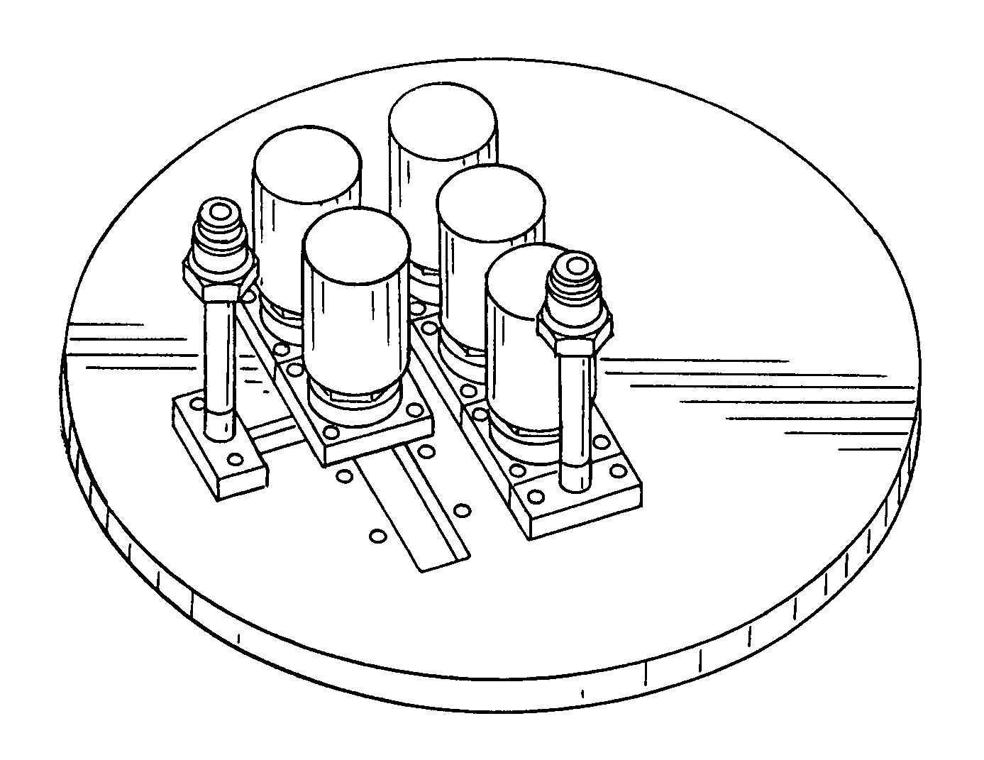
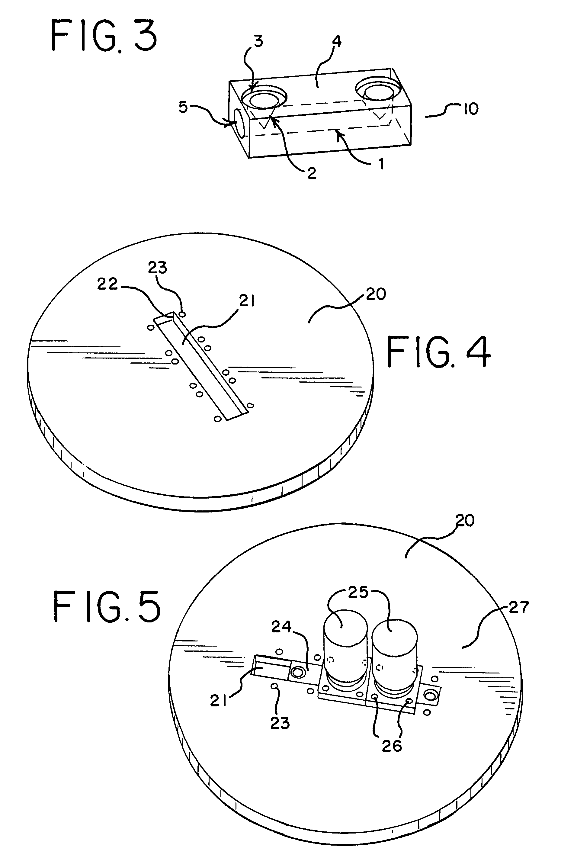
[0033]A substantially square or rectangular shaped modular fluid insert is preferred for use in adapting MSM fluidic components directly to the surface of monolithic structures such as containment structures on chemical canisters and vacuum or pressure vessels, or semiconductor wafer processing chambers, or surfaces integral to larger fluidic conduits. More preferably, the overall dimensions of the insert may be seen to be ...


PUM


Abstract

A modular insert and monolithic structure is disclosed where the inserts are embedded in a slot in the monolithic structure to allow MSM components to be mounted directly to the planar surface of the monolithic structure.

Description

PRIORITY[0001]This application claims priority to provisional patent application U.S. 60 / 859,423, filed Nov. 16, 2006, entitled FLUID TRANSPORT IN MONOLITHIC STRUCTURES.FIELD OF THE INVENTION[0002]The present invention relates to the field of fluid handling devices generally, and specifically to a system and assembly for allowing process fluid flow between a monolithic structure and modular surface mounted (“MSM”) fluidic components used in the semiconductor industry.BACKGROUND OF THE INVENTION[0003]The term “monolithic structure” refers to mechanical elements that are inherently part of structures that receive process fluids. Typically, these monolith structures are unitary in design and can take the form of lids for fluid receiving chambers, such as chemical canisters (also known as chemical ampoules), semiconductor wafer processing chamber lids, single-gas and multiple-gas manifolds, and other pressure / vacuum chambers. Fluid communication into, and out of, these process fluid rec...

Claims


Application Information

Patent Timeline
Patent Type & Authority Patents(United States)
IPC IPC(8): F16K27/00
CPCF15B13/0825F16K27/003Y10T137/2224Y10T137/87885
Inventor ERIKSSON, MARK L.REX, DENNIS
Owner TALON INNOVATIONS CORP
Why Eureka
Try Eureka