Brazing process and material for repairing a component

a brazing process and component technology, applied in the direction of turbines, manufacturing tools, soldering apparatus, etc., can solve the problems of poor mechanical properties of the resulting brazing, difficulty in consistently using optimal quantities of brazing material, and cracks that can develop in the thermally hostile environment near the combustor, etc., to achieve the effect of higher melting temperatur

Active Publication Date: 2010-09-07
GENERAL ELECTRIC CO
View PDF13 Cites 44 Cited by
  • Summary
  • Abstract
  • Description
  • Claims
  • Application Information

AI Technical Summary

Benefits of technology

[0007]According to a preferred aspect of the invention, the braze paste is able to form a dense brazement capable of repairing both relative narrow and wide through-cracks, as well as adjoining through-holes, as a result of the braze paste becoming sufficiently fluid at brazing temperatures to completely fill cracks of various widths.

Problems solved by technology

Impingement plates are typically thin, one nonlimiting example being about 0.092 inch (about 2.3 mm) in thickness, with the result that through-cracks can develop in the thermally hostile environment near the combustor.
Difficulties associated with such braze materials include the difficulty of consistently using optimal quantities of the braze material, accurately placing the braze material, and accurately shaping and sizing the braze material for the area being brazed.
Other shortcomings may include low densities and excessive porosity and voids created during binder burn-off, resulting in poor mechanical properties for the resulting brazement.

Method used


Image

  • Brazing process and material for repairing a component
  • Brazing process and material for repairing a component
  • Brazing process and material for repairing a component

Examples


Embodiment Construction

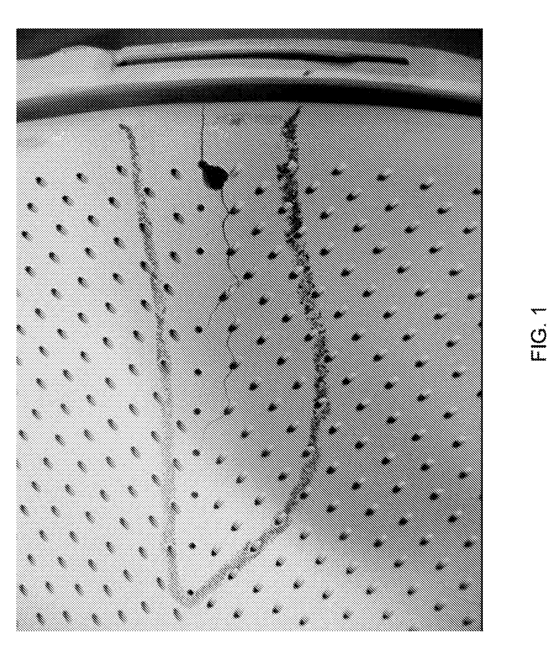
[0019]FIG. 1 shows a surface region of an impingement plate of a type adapted to serve as a radiation shield for a combustion liner cap assembly of a gas turbine engine. The impingement plate is shown as being formed to have a large number of effusion cooling holes that promote the ability of the impingement plate to shield the cap assembly from thermal radiation emitted by the combustor of a gas turbine engine. The impingement plate is formed of a material capable of withstanding the hostile thermal environment of a gas turbine combustor. A notable example of such a material is Hastelloy X, a nickel-base superalloy whose nominal composition has been reported in the literature as, in weight percent, Ni-0.1C-22Cr-9Mo-0.5W-1Co-19Fe. Another notable example of an alloy suitable for impingement plates includes, but is not limited to, Haynes 230, whose nominal composition has been reported in the literature as, in weight percent, Ni-0.1C-22Cr-2Mo-14W-0.3Al-0.5Mn-0.4Si-0.02La.

[0020]Imping...


PUM

PropertyMeasurementUnit
thicknessaaaaaaaaaa
widthaaaaaaaaaa
porosityaaaaaaaaaa

Abstract

A process and braze paste suitable for filling and closing voids in relatively thin wall sections of high temperature components, such as an impingement plate of a combustor of a gas turbine engine. The process entails applying at least a first braze paste to the crack to form a braze paste patch comprising powders of first and second alloys and an organic binder. The first alloy has a higher melting temperature than the second alloy, and the powders of the first and second alloys are present in the braze paste patch at a weight ratio of about 30:70 to about 70:30 weight percent. The braze paste patch is then heated to burn off the binder and melt at least the powder of the second alloy to form a brazement within the crack that contains particles of the first alloy dispersed in a matrix formed by the second alloy.

Description

BACKGROUND OF THE INVENTION[0001]The present invention generally relates to brazing processes and materials for repairing components that operate at high temperatures. More particularly, this invention relates to a process of filling cracks and other defects in hot gas path components of gas turbines, including through-thickness cracks in relative thin components such as the impingement plate of a gas turbine engine.[0002]Hot gas path components of gas turbines are typically formed of nickel, cobalt or iron-base superalloys with desirable mechanical and environmental properties for turbine operating temperatures and conditions. A particular example is an impingement plate that protects the aft end of a combustion liner cap assembly, through which fuel nozzle assemblies extend into the combustor of a gas turbine engine. Impingement plates may be equipped with effusion cooling holes to promote the ability of the impingement plate to serve as a radiation shield for the cap assembly. Im...

Claims


Application Information

Patent Timeline
Patent Type & Authority Patents(United States)
IPC IPC(8): B23K31/00B23P6/04
CPCB23K1/0018B23K35/025B23K35/22B23K35/3033B23K35/362C22C19/05B23K35/34Y10T29/49318B23K2201/001F05B2230/80B23K2101/001
Inventor JOHNSON, JERE A.CHANNEL, TIMOTHY
Owner GENERAL ELECTRIC CO
Why Eureka
Try Eureka