Double temperature sensor

a technology of temperature sensor and sensor body, applied in the field of double temperature sensor, to achieve the effect of simple manufactur

Active Publication Date: 2010-09-07
DRAGERWERK AG
View PDF14 Cites 16 Cited by
  • Summary
  • Abstract
  • Description
  • Claims
  • Application Information

AI Technical Summary

Benefits of technology

[0006]Based on this, the basic object of the present invention is to perfect a double temperature sensor such that simple manufacture is guaranteed with reproducible precision.
[0008]The advantages gained with the present invention are that tolerances of the heat transfer coefficient can be minimized in the double temperature sensor according to the present invention.
[0009]This is accomplished especially by the temperature sensor elements being arranged in a heat flux insulation block. The insulation material of the heat flux insulation block has an essentially homogeneous structure. It is guaranteed as a result that the heat flux between the two temperature sensor elements is low and can be determined in advance. The double temperature sensor according to the present invention can be manufactured at a very low cost, preferably according to the injection molding process. An additional operation for applying the heat-conducting housing parts is eliminated.
[0010]In a preferred embodiment, the heat flux insulation block consists of a polyether ether ketone (PEEK) material, which can be easily processed according to the injection molding process, on the one hand, and is characterized, on the other hand, by a lower heat conductivity. Other preferred insulation materials of the heat flux insulation block have a heat conductivity between 0.05 W / mK and 0.3 W / mK.
[0011]The heat flux insulation block is preferably of a cylindrical shape with two lateral openings, such that the temperature sensor elements can be introduced into and fixed in the openings. However, it is also conceivable that the temperature sensor elements are embedded, together with the electric connections, in the heat flux insulation block by the injection molding process. In another embodiment, the electric connections of the temperature sensor elements may be arranged in the heat flux insulation block in the spiral, circular, meandering, zigzag or star form or in the form of a polygon. It is thus possible to reduce the heat fed in or removed via the electric connections of the temperature sensor elements based on an external temperature disturbance and to correct a temperature measurement that is incorrect as a result. Moreover, the heat conduction of the electric connection can be reduced by the use of reduced wire cross sections and the use of nickel wire instead of copper wire. In another preferred embodiment of the double temperature sensor according to the present invention, the surface of the heat flux insulation block, which surface is intended to be placed on the skin surface, has a concave shape. Optimal heat transfer of the skin temperature to the temperature sensor element is thus advantageously guaranteed. Reducing the section of the heat flux insulation block in the axial direction between the temperature sensor elements makes possible a more compact shape of the double temperature sensor, because the distance between the temperature sensor elements can be reduced due to the air which hinders the heat flux, while the heat transfer coefficient remains comparatively equal.

Problems solved by technology

The different materials, especially the heat-insulating layers and the heat-conductive layers arranged in parallel, which must be connected during the manufacture, are disadvantageous in the design of the prior-art double temperature sensor.
However, the manufacturing tolerances should be as low as possible in order to avoid an individual calibration of the double temperature sensors, which causes costs.

Method used


Image

  • Double temperature sensor
  • Double temperature sensor
  • Double temperature sensor

Examples


Embodiment Construction

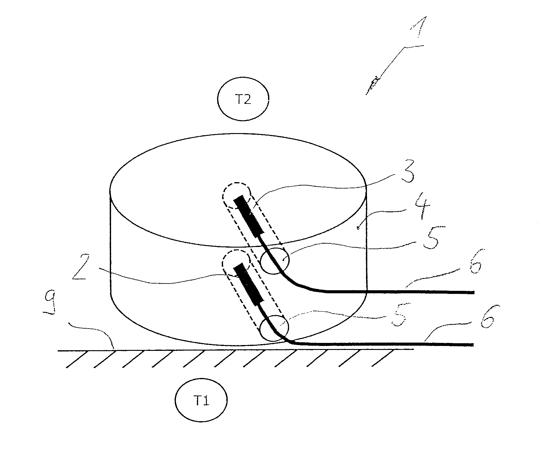
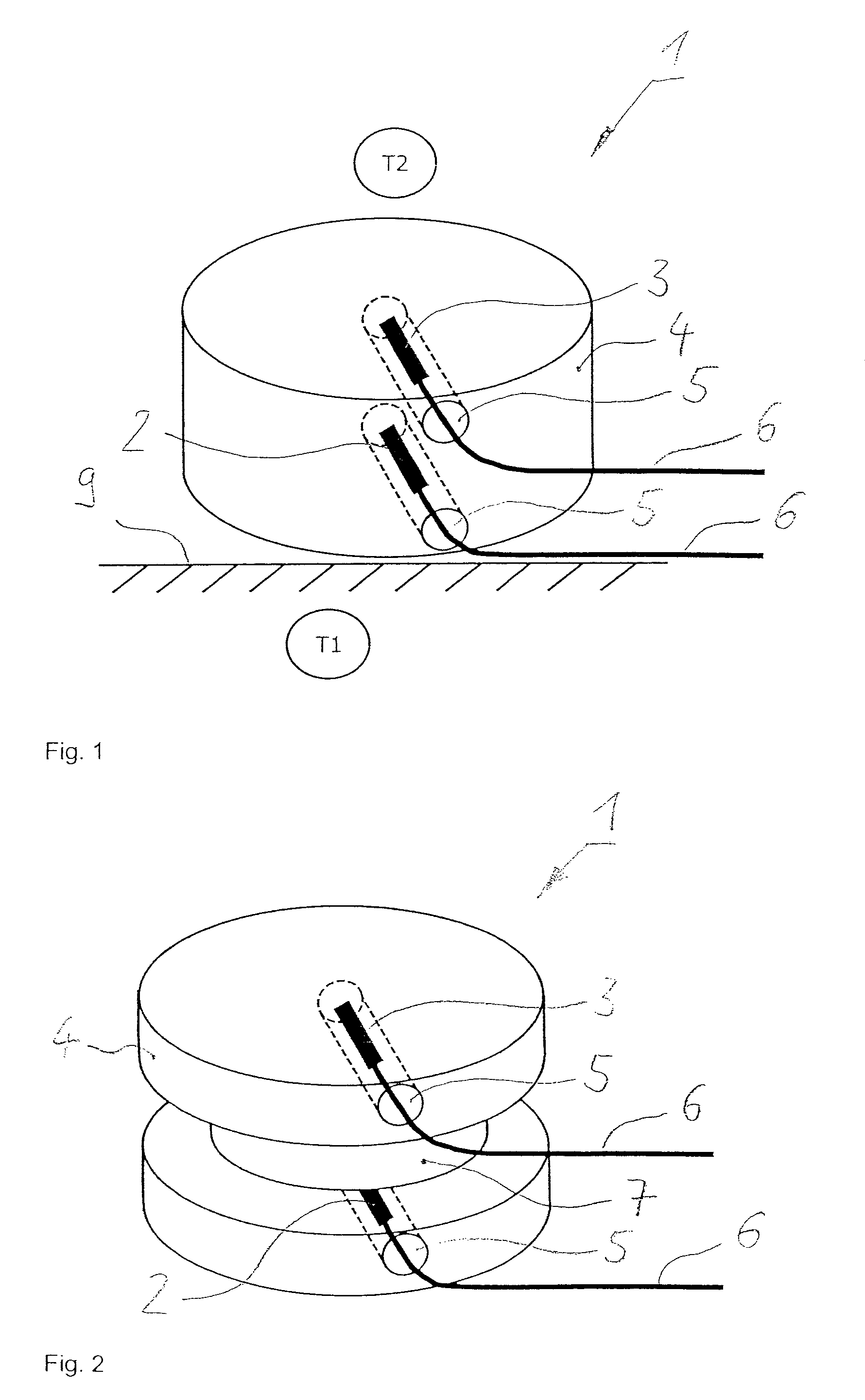
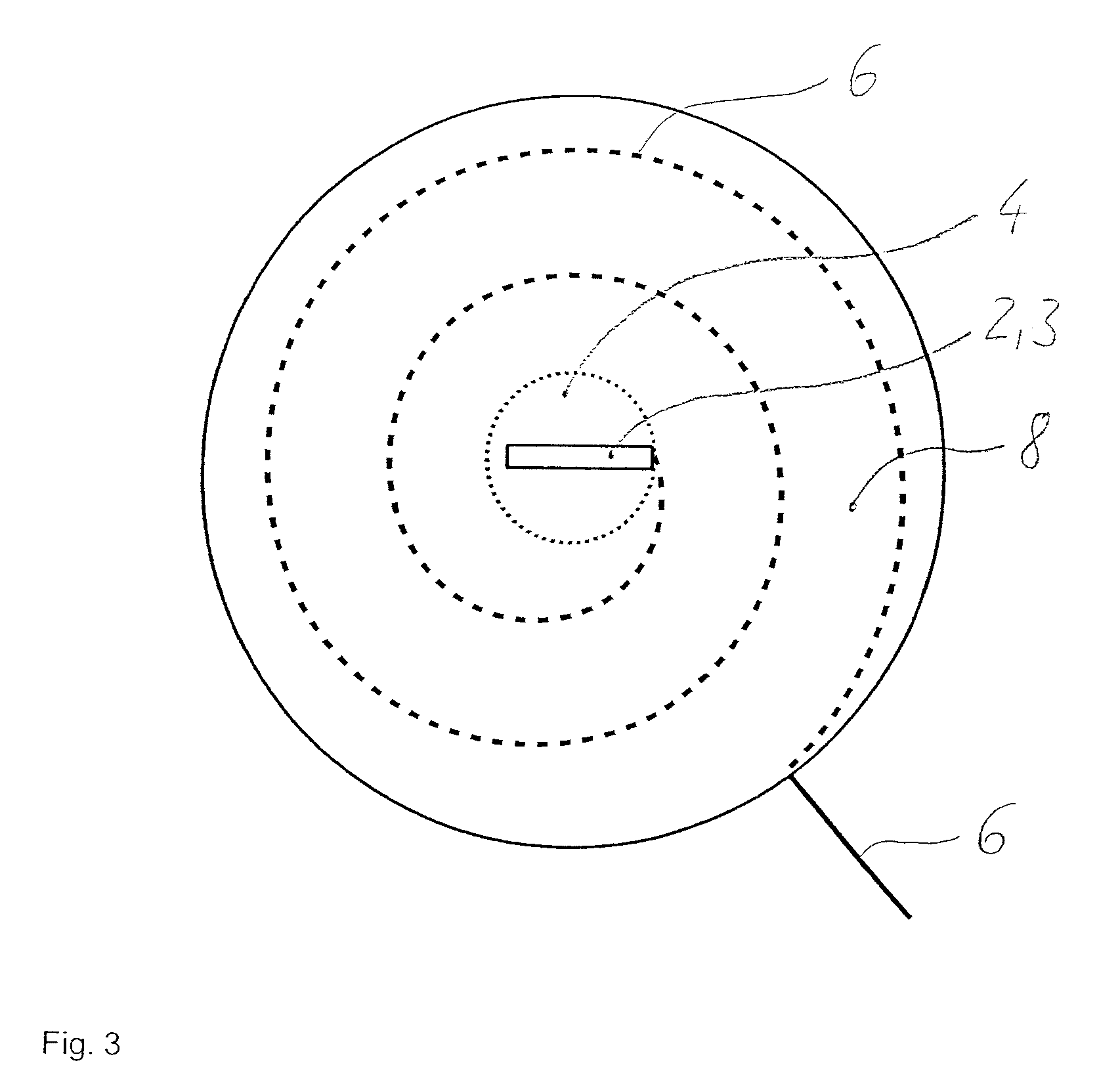
[0019]Referring to the drawings in particular, FIG. 1 shows a double temperature sensor 1 according to the present invention of a cylindrical design. The double temperature sensor 1 has a heat flux insulation block 4, which is shaped as a housing and is made in one piece. Two temperature sensor elements 2, 3 are arranged in the heat flux insulation block 4 at spaced locations one on top of another and near the surface. The two temperature sensor elements 2, 3 are introduced into openings 5 provided in the heat flux insulation block 4 and are fixed in these. The fixation may be carried out by bonding in the temperature sensor elements 2, 3. The double temperature sensor 1 according to the present invention of a cylindrical shape has a design of a small size with a height of 6 mm and a diameter of 10 mm. However, embodiments with different dimensions may be provided as well. The insulation material of the heat flux insulation block 4 is homogeneous, so that uniform heat flux is guaran...


PUM

PropertyMeasurementUnit
diameteraaaaaaaaaa
heightaaaaaaaaaa
lengthaaaaaaaaaa

Abstract

A double temperature sensor is provided for measuring a near-surface temperature of the ambient air and the temperature of the skin surface (9). A heat flux insulation block (4) is made of an insulation material in one piece as a housing. Two temperature sensor elements (2, 3) with respective electric connections (6) belonging to them are arranged in the heat flux insulation block (4) one on top of another at spaced locations from one another and near the surface.

Description

CROSS REFERENCE TO RELATED APPLICATIONS[0001]This application claims the benefit of priority under 35 U.S.C. §119 of German Patent Application DE 10 2007 002 369.5 filed Jan. 17, 2007, the entire contents of which are incorporated herein by reference.FIELD OF THE INVENTION[0002]The present invention pertains to a double temperature sensor for measuring a near-surface temperature of the ambient air and the temperature of the skin surface and a process for the use of a double temperature sensor for determining the core temperature of a patient as well as a process for the simultaneous measurement of the skin temperature of a patient and the temperature of the patient's environment.BACKGROUND OF THE INVENTION[0003]Double temperature sensors are used in the known manner to measure a near-surface temperature of the ambient air and of the skin surface. They are used, for example, in gas masks and breathing equipment for detecting and monitoring the body temperature in order to make it pos...

Claims


Application Information

Patent Timeline
Patent Type & Authority Patents(United States)
IPC IPC(8): G01K7/00G01K1/00G01K3/00
CPCG01K1/16G01K1/165G01K13/002G01K13/20
Inventor SATTLER, FRANKSTARK, HARTMUT
Owner DRAGERWERK AG
Why Eureka
Try Eureka