Lens blank and lens elements as well as method for their production

a technology of lens elements and blanks, applied in the field of lens blanks and lens elements as well as their production methods, can solve the problems of unfavorable manner, precise effect of strain shift, and cannot be clarified by means of experiments or elaborate simulations, and achieve favorable strain distribution and reduce waste

Active Publication Date: 2010-09-07
CARL ZEISS SMT GMBH
View PDF7 Cites 6 Cited by
  • Summary
  • Abstract
  • Description
  • Claims
  • Application Information

AI Technical Summary

Benefits of technology

[0023]It is proposed that an asymmetrical lens element be cut only from a partial volume of the tempered blank with a thickness of less than 70% of the entire thickness of the tempered blank. While in the method shown in FIG. 5a-c for producing lenses the edge region of the lenses are located in the corners of the tempered blank, which corners have a high SBR, during manufacture of a lens element these regions can be made so as to be less thick. Moreover, according to the invention the direction and amount of the strain along the lens element can better be evened out so that the shift in tension during cutting of the lens elements is reduced. In this context the fact that in the partial volume the minimum of the strain birefringence is not located in the middle but instead is arranged asymmetrically has an advantageous effect.
[0057]Yet another aspect is implemented in a projection lens for use in microlithography, which lens comprises at least one lens element as described above. Such a projection lens forms part of a projection exposure apparatus for microlithography, which apparatus, apart from the projection lens, also comprises an illumination system for the homogeneous illumination of a structure on a mask. The projection lens is used for size-reducing imaging of this structure onto a light-sensitive substrate. As a result of the lens element the strain birefringence, and consequently also the imaging characteristics, of the projection lens can be enhanced.

Problems solved by technology

A body with high density gradients that are oriented differently, which body is formed by the lens elements 4, 5, thus behaves in an unfavorable manner in the sense that the shift in strain can be calculated in advance only with considerable difficulty and in that the precise effect of such shift in strain can only be clarified by means of experiments or by means of elaborate simulation.
If asymmetrical lens elements are cut from tempered blanks in a manner described in FIG. 5b and FIG. 5c, the unfavorable effects described above thus occur, namely on the one hand a high SBR observed in the edge regions of the lens elements, and on the other hand a shift in the strain after cutting the lens elements, which shift results in a shift of the SBR.

Method used


Image

  • Lens blank and lens elements as well as method for their production
  • Lens blank and lens elements as well as method for their production
  • Lens blank and lens elements as well as method for their production

Examples


Embodiment Construction

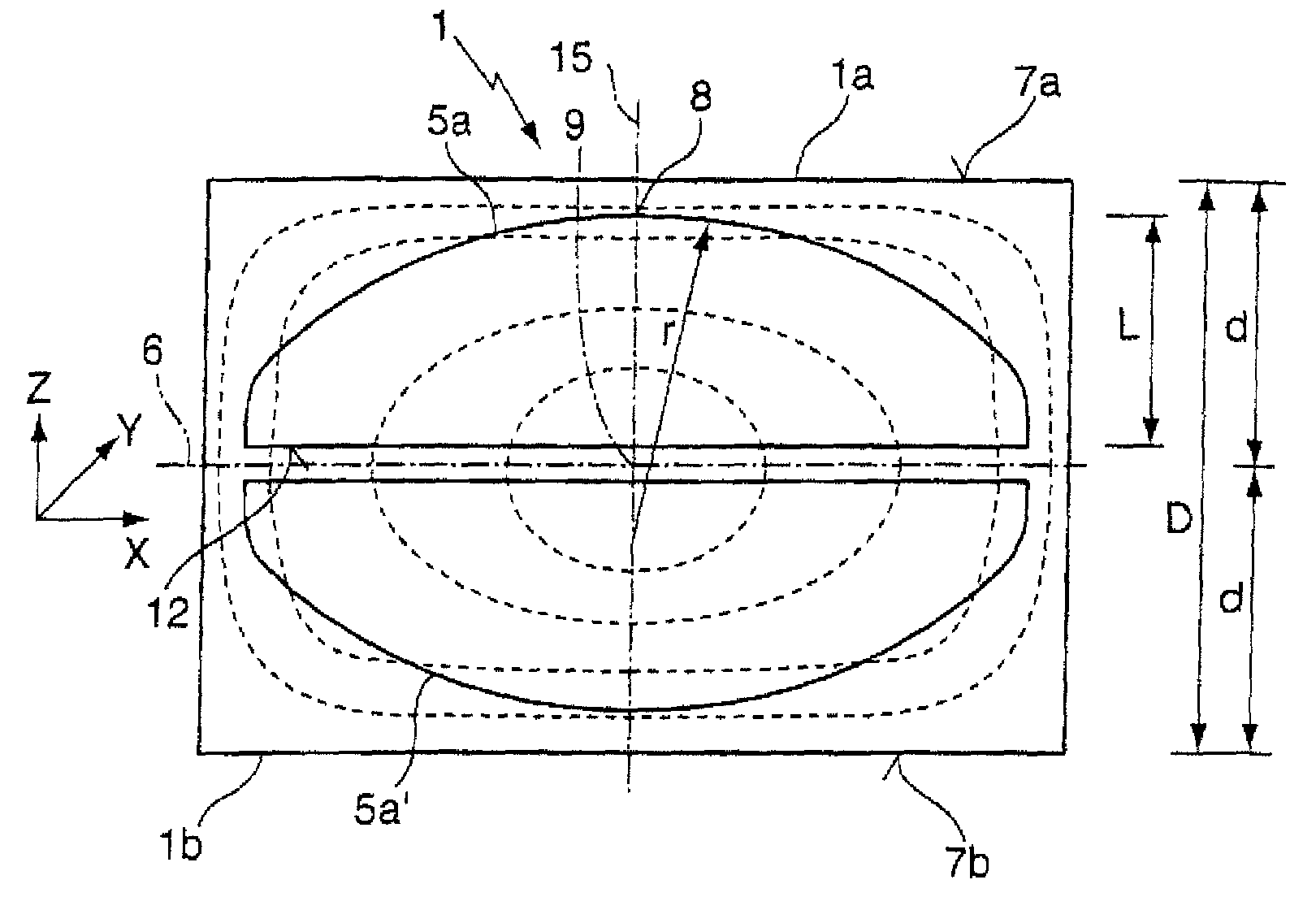
[0067]FIG. 1 shows a section of a tempered cylindrical blank 1 which comprises a thickness D of 10 cm between a first and a second end face 7a, 7b, with the density distribution of said blank 1 essentially corresponding to the density distribution shown in FIG. 5. In this arrangement the cylindrical blank 1 and thus the density distribution are rotationally symmetrical in relation to a longitudinal axis 15 that extends in z-direction. The density is at its maximum in the center, ire at the point of intersection between a mid-plane 6 of the tempered blank 1 and the longitudinal axis 15; this is also where the strain birefringence of the tempered blank 1 is at its minimum 9.

[0068]In order to manufacture two piano-convex lens elements 5a, 5a′ the tempered blank is divided, along the mid-plane 6 that serves as a cutting plane, into a first partial volume 1a and a second partial volume 1b, which partial volumes comprise an identical thickness d of somewhat less than 5 cm. The two plano-c...


PUM

PropertyMeasurementUnit
operating wavelengthaaaaaaaaaa
wavelengthsaaaaaaaaaa

Abstract

A method for manufacturing a preferably asymmetrical lens element (5a) from a tempered blank (1) is characterized by: producing the lens element (5a) from a first partial volume (1a) of the tempered blank (1), whose thickness d is less than approximately 70%, preferably less than approximately 60%, particularly preferably less than approximately 50% of the thickness D of the tempered blank (1). Preferably, from a second partial volume (1b) of the tempered blank (1) at least a further lens element (5a′) is produced, wherein before the lens elements (5a, 5a′) are produced the tempered blank (1) is divided into the first and second partial volume (1a, 1b).

Description

CROSS-REFERENCE TO RELATED APPLICATIONS[0001]This application claims priority under 35 U.S.C. §119(a) to German Patent Application No. 10 2006 031 995.8, filed on Jul. 11, 2006, the entire contents of which are hereby incorporated by reference.BACKGROUND OF THE INVENTION[0002]The invention relates to a method for producing a preferably asymmetrical lens element from a tempered blank; to a lens blank for microlithography, preferably with cylindrical geometry; as well as to lens elements and to a projection lens with such a lens element.[0003]Lens elements made of fused silica are, for example, used in projection exposure apparatuses for microlithography. In such apparatuses, radiation generated by a usually pulsed laser at an operating wavelength of e.g. 248 nm (KrF laser) or 193 nm (ArF laser) is imaged to a sharply delimited very homogeneously illuminated image field by means of an illumination system, in which image field a mask is arranged. A pattern that is provided on the mask ...

Claims


Application Information

Patent Timeline
Patent Type & Authority Patents(United States)
IPC IPC(8): G02B3/00
CPCG02B1/02G03F7/70341G02B3/06G02B1/08
Inventor EVA, ERIC
Owner CARL ZEISS SMT GMBH
Why Eureka
Try Eureka