Multi-stage coil for transformer, and coil winding method and apparatus for manufacturing the same

a transformer and multi-stage technology, applied in the direction of manufacturing tools, magnets, magnetic bodies, etc., can solve the problems of difficult to modify the coil shape, short circuits, breakage of the insulating coating, etc., and achieve the effect of increasing the capacity of the winding coil and the capacity of the mold transformer

Inactive Publication Date: 2010-09-14
HITACHI IND EQUIP SYST CO LTD
View PDF13 Cites 0 Cited by
  • Summary
  • Abstract
  • Description
  • Claims
  • Application Information

AI Technical Summary

Benefits of technology

[0016]According to the present invention, since at least two or more electric wires are used, multiple stage winding is achieved by stacking the wires in layers while winding those into a disk shape, and increase in capacity of a winding coil for a transformer can be realized, the transformer can be developed to a large model. Further, the number of wires can be increased to be two or more, and a route for applying the coil to a larger model can be achieved. Further, according to the present invention, the sectional area of the combined electric wires can be made large without changing the size of the respective electric wires, and therefore, increase in capacity of a mold transformer can be realized. Further, in the winding apparatus, it is possible to realize in-line operation of the working process such as flattening work.

Problems solved by technology

Therefore, when the radius of curvature is small, or the rolling deformation amount in the sheet thickness direction by the pressure roller is large, the insulating material such as an insulating sheet or an insulating film which is wound on the electric wire easily breaks at the time of rolling, and therefore, there is the fear of occurrence of short circuit and the like.
Further, while the shape of the coil may change due to the inclination of the pressure roller, the pressing amount against the electric wire, the size variation of the electric wire material and the variation of a material characteristic such as malleability, it is difficult to modify the coil shape.
Further, in the case of the art disclosed in JP-A-2000-69721, it is nothing but an art of providing a coil shape by automatically winding a flat conducting wire (flat rectangular electric wire) formed by rolling a round conducting wire with insulating coating, and there is the fear of easily causing breakage of the insulating coating, and reduction in conductor occupation rate and the like in the curve portion (corner portion) of the coil.
However, in the case of increasing the size in the case of the single wire, there is a limit in manufacturing, such as a technical problem in manufacturing the electric wire itself, cost, a technical problem of the manufacturing device itself such as a wire winding apparatus and the like.

Method used


Image

  • Multi-stage coil for transformer, and coil winding method and apparatus for manufacturing the same
  • Multi-stage coil for transformer, and coil winding method and apparatus for manufacturing the same
  • Multi-stage coil for transformer, and coil winding method and apparatus for manufacturing the same

Examples


embodiment 1

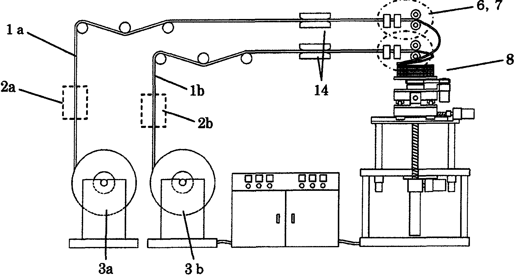
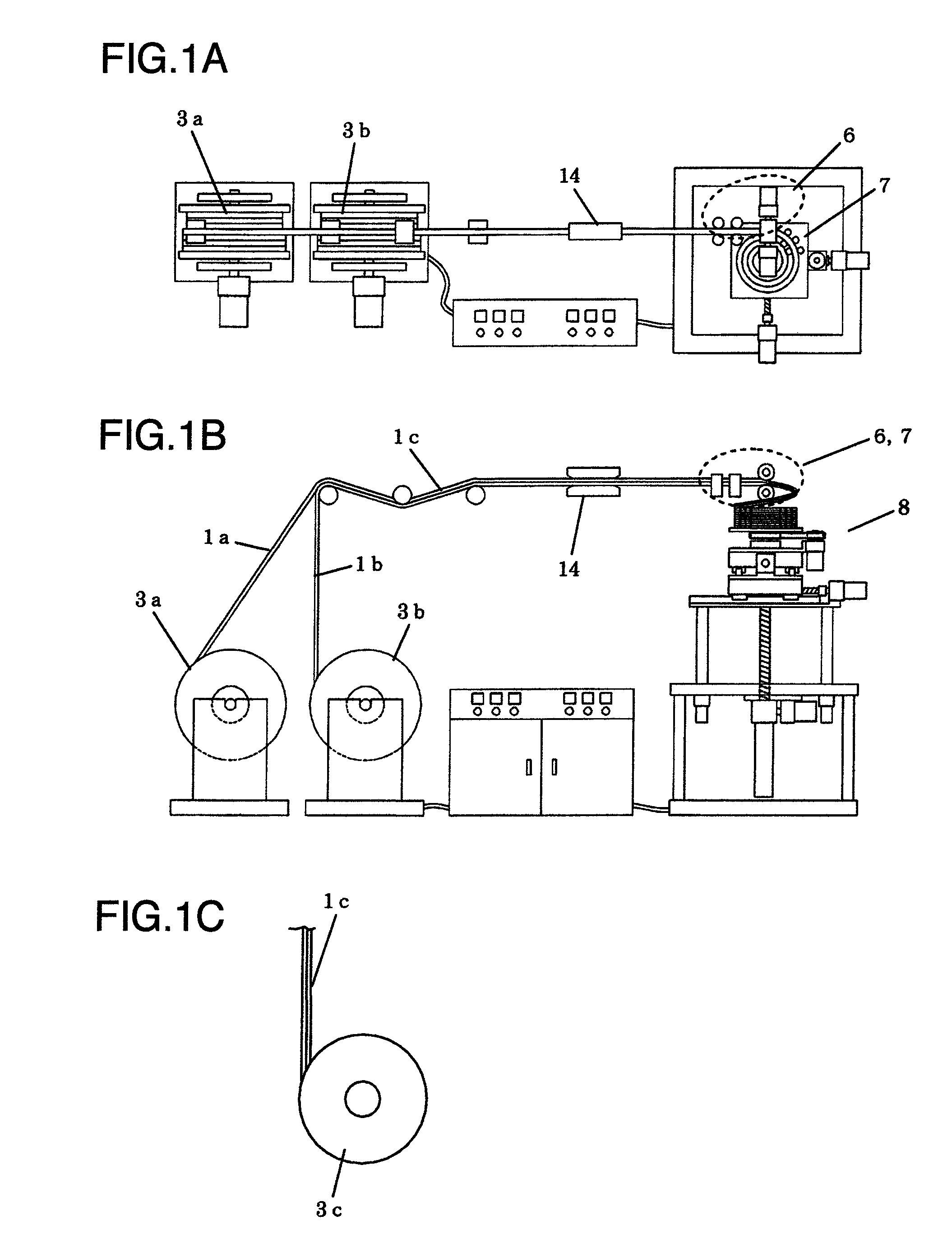
[0030]FIGS. 1A to 1C are general schematic views showing embodiment 1 of a winding apparatus of a multi-stage coil for a transformer according to the present invention, FIG. 1A is a plane view, and FIG. 1B is a front view. As shown in FIGS. 1A to 1C, flat rectangular electric wires 1a and 1b which have been wound on individual wire drums 3a and 3b are superimposed in a vertical direction immediately after being fed from the wire drums 3a and 3b, and are supplied to a wind-up part 8 in that state. The wind-up part 8 is adjustable in position in a plane, and is provided so as to be capable of ascending and descending by a mechanism like a screw mechanism in accordance with stacking of the coil. A supply part of the flat rectangular electric wires 1a and 1b includes a feeding device 14 and various guide rollers. The flat rectangular electric wires 1a and 1b are fed to a forming part (integrally combining part) 6 while being fed by a predetermined amount by the feeding device 14. The wi...

embodiment 2

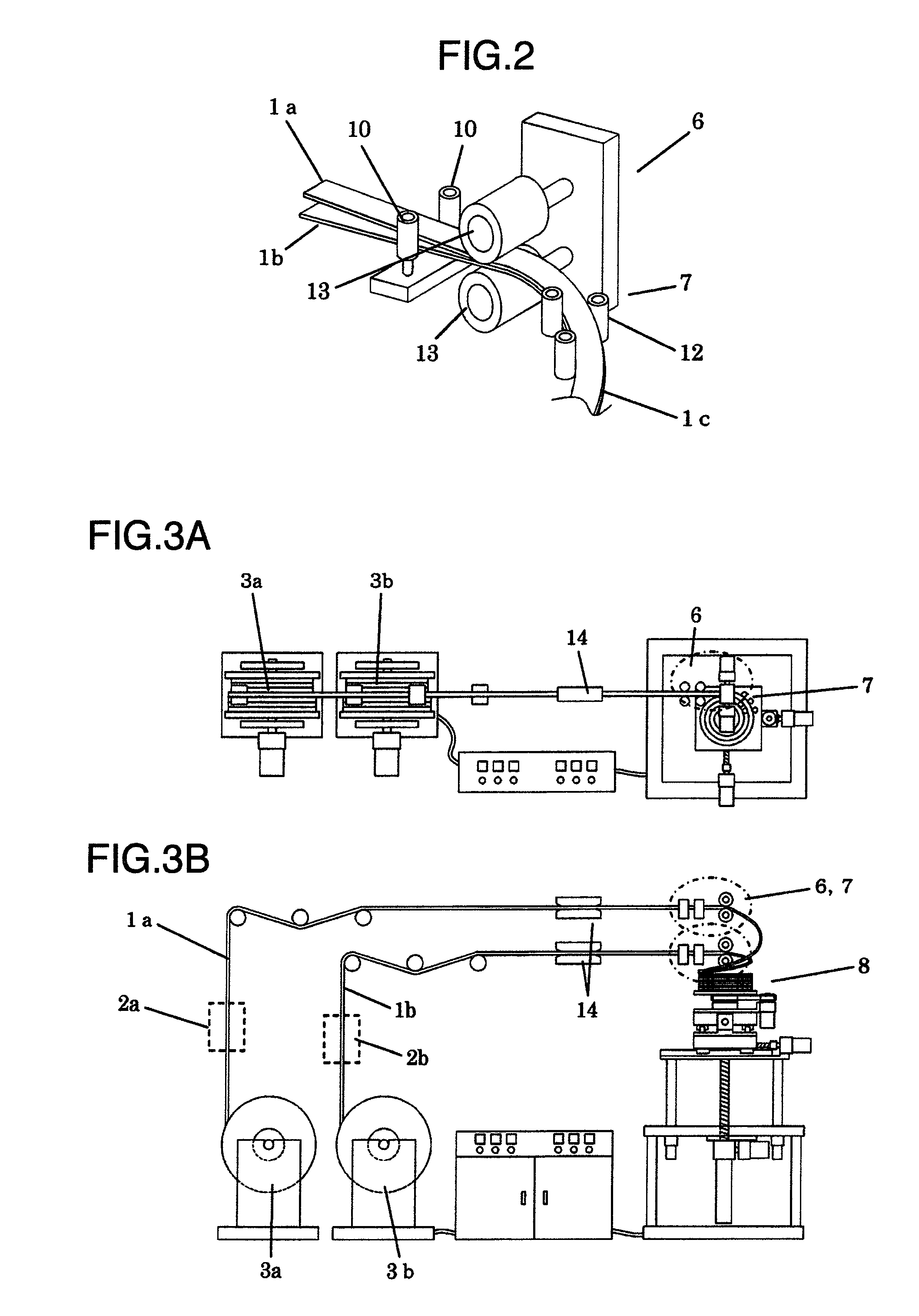
[0034]FIGS. 3A and 3B are general schematic views showing embodiment 2 of the winding apparatus of a multi-stage coil for a transformer according to the present invention, FIG. 3A is a plane view, and FIG. 3B is a front view. In embodiment 2 shown in FIGS. 3A and 3B, a supply part is two supply parts respectively having routes in which the flat rectangular electric wires 1a and 1b which are wound around individual wire drums 3a and 3b are vertically disposed individually, and the flat rectangular electric wires 1a and 1b which are respectively supplied by the supply parts are formed by separate forming parts 6 and 6 respectively. The other structure as an apparatus is similar to the one included in embodiment 1 except for the electric wire working device, and therefore, redundant explanation will be omitted.

[0035]FIG. 4 is a perspective view showing the forming part of the winding apparatus shown in FIGS. 3A and 3B. As shown in FIG. 4, the forming unit 7 in the forming part 6 includ...

embodiment 3

[0037]FIGS. 7A and 7B are general schematic views showing embodiment 3 of the winding apparatus of the multi-stage coil for a transformer according to this invention, FIG. 7A is a plane view, and FIG. 7B is a front view. Embodiment 3 which is shown in FIGS. 7A and 7B adopts a disk winding machine as shown in Japanese Patent No. 3996005 described above, in other words, a winding apparatus in which two or more systems including a system extending from the wire drum 3a to a forming part 6a through the feeding device 14, and a system extending from the wire drum 3b to a forming part 6b through the feeding device 14 are respectively disposed in a plane layout, and the electric wires respectively formed in the forming parts 6a and 6b in the respective systems are superimposed at the wind-up part 8 disposed near the center so as to be stacked in layers into a disk winding shape. The winding apparatus is an apparatus which may be called a plane double type.

[0038]In embodiment 3, the feeding...


PUM

PropertyMeasurementUnit
shapeaaaaaaaaaa
sizeaaaaaaaaaa
thicknessaaaaaaaaaa

Abstract

At least two or more flat rectangular wires having been fed separately or simultaneously (two or more are superimposed) are integrated by being pinched in a width direction and a thickness direction by at least two or more pairs of rollers and are rolled and formed simultaneously in a forming part to be formed into two or more flat rectangular electric wires. The two formed electric wires are stacked in layers in a wind-up part while being wound into a disk shape to provide a multi-stage coil. Two or more systems up to the forming part of the winding apparatus may be disposed in a planar layout. Each system may supply one flat rectangular electric wire separately, and the supplied electric wires may be stacked in layers in the wind-up part while being superimposed. The coil may be molded entirely.

Description

INCORPORATION BY REFERENCE[0001]The present application claims priority from Japanese application No. 2008-128193 filed on May 15, 2008, the content of which is hereby incorporated by reference into this application.BACKGROUND OF THE INVENTION[0002]1. Field of the Invention[0003]The present invention relates to a multi-stage coil for a transformer which is formed by winding at least two or more flat rectangular electric wires in multiple stages and is used for a mold transformer, and to a winding method and apparatus for manufacturing the same.[0004]2. Description of Related Art[0005]Conventionally, there has been described an art in which in order to manufacture a multi-stage coil efficiently, a flat rectangular electric wire is rolled in a sheet thickness direction by paired pressure rollers by using motor power, and thereafter, the flat rectangular electric wire is wound concentrically to form an annular coil, and particularly, there has been stated that the above described paire...

Claims


Application Information

Patent Timeline
Patent Type & Authority Patents(United States)
IPC IPC(8): B65H18/08B65H51/015B65H39/14
CPCH01F41/0625H01F41/0691H01F27/29H01F27/327Y10T29/5313Y10T29/49071Y10T29/4902H01F41/069H01F41/077
Inventor MARUYAMA, EISUKEOGATA, TOSHIOISHIZUKI, JYUNICHI
Owner HITACHI IND EQUIP SYST CO LTD
Why Eureka
Try Eureka