Prefabricated lightweight concrete structure including columns

a lightweight concrete and prefabricated technology, applied in the field of lightweight monolithic concrete structures, can solve the problems of not facilitating hollow rectangular shaped columns, lightweight concrete columns, devoid of smooth or ornate surface features of cylindrical columns, etc., and achieves the effects of strong and durable, easy transportation, and easy transportation

Inactive Publication Date: 2010-09-14
NATURES GATE DESIGNS
View PDF23 Cites 11 Cited by
  • Summary
  • Abstract
  • Description
  • Claims
  • Application Information

AI Technical Summary

Benefits of technology

[0027]The present invention provides a process for making prefabricated, lightweight, modular, concrete, structures such as columns. These lightweight structures including columns and end caps have a very smooth outer surface, which has detailed decorative designs and is resistant to damage by chipping due to the incorporation of short length glass fibers in the face coat that carries the detailed design. This face coat is supported by a second undercoat, which has long length glass fibers embedded in the cement, providing strength to the column. Surprisingly, this glass fiber reinforced concrete (GFRC) column can be handled by machinery, such as forklift trucks and the like, and readily transported without damage or breakage. This advantageous feature is likely due to the reinforcing strength provided by the glass fibers. The integrity of the short and long length glass fibers during concrete cement cure, which forms acicular or needle shaped hydrated calcium aluminate crystals, is maintained by the use of a polymeric coating such as an acrylic polymer that protects the glass fibers. The polymeric layer also provides load coupling between the cement matrix and the glass fiber, thereby strengthening the GFRC column.
[0029]The concrete structure or column manufacturing process involves assembly of two face pairs which are hinged, each of the face pairs comprising two adjacent faces with details engraved in reverse of the column face design. The face pairs are opened out first and are sprayed with a first GFRC slurry coating that has the short fibers, hardened to a tacky state and then sprayed with the second GFRC slurry coating containing long length glass fibers. The second layer is allowed to harden to a tacky state after elapse of appropriate time. The hinge is now closed, bringing into contact the two face pairs, and thereby forming a hollow column. The joint line at the hinge and at the location opposite to the hinge in the closed column mold is sprayed with the second GFRC slurry with long length glass fibers to complete the monolithic column formation. Since the second GFRC slurry has long length glass fibers, these fibers bridge the joint line, providing strength to the column thus formed. The monolithic hollow column is provided at one end of the closed column mold with a metallic base frame suited for attachment of the hardened column to a cement footing or bolted arrangement. The opposite end of the closed column mold is shaped in the tacky state to have precise dimensions suited for accepting decorative top castings so that various designs of columns can be assembled at the installation site according to the preferences of the user. The column is allowed to harden completely, and the adjoining tacky joints cure to form a monolithic high strength lightweight glass fiber reinforced hollow concrete structure.
[0031]The concrete structure or column manufacturing process produces a lightweight column that is easy to ship. It uses a time-efficient molding process to produce large numbers of prefabricated columns. Because the columns are substantially hollow, they are lightweight and easy to transport. However, because the columns are composed of a glass fiber reinforced concrete, they are very strong and durable. Further, a metal base frame provides a strong attachment point to attach the columns to concrete footings. The opening of the hollow column opposed to the metallic frame has precise dimensions to accept various designs of ornamental top column structures providing modular assembly of columns with variable design geometry. The finished column includes a prefabricated cap on its top.

Problems solved by technology

However, these cylindrical columns are devoid of smooth or ornate surface features.
These forms do not facilitate casting of hollow, lightweight concrete columns.
The mold is suited for casting cylindrical solid concrete columns and does not facilitate casting hollow rectangular shaped columns.
The space between the stones contains plaster of Paris, which is easily damaged.
The latex support needs to be removed and this removal also may damage the Plaster of Paris, adversely affecting the appearance of the column produced.
The pipe may not be readily removable, and the column is not hollow.
This form does not produce hollow lightweight columns.
The surface of the barrier is not ornate or smooth, due to the presence of long length glass fibers in the cement.
Since all the sides of the structure are cast together, there is a possibility that cement slurry will drip down, particularly from vertical and overhanging surfaces.
These structures are therefore unsuited for load bearing applications such as free-standing columns.
Incorporation of random fibers first in the mold followed by infiltration of low viscosity slurry results in fibers sticking through the surface, forming a rough, poor-quality cast concrete surface.
It is not hollow in construction and is, therefore, heavy.
The protrusions into the concrete will weaken the concrete core.
This process does not produce hollow glass fiber reinforced concrete columns.
These penetrations generally weaken the concrete core.
Removal of this form will be difficult if the block column external surface has a brick like structure and these features have reentrant surfaces and cannot be easily removed.

Method used


Image

  • Prefabricated lightweight concrete structure including columns
  • Prefabricated lightweight concrete structure including columns
  • Prefabricated lightweight concrete structure including columns

Examples


Embodiment Construction

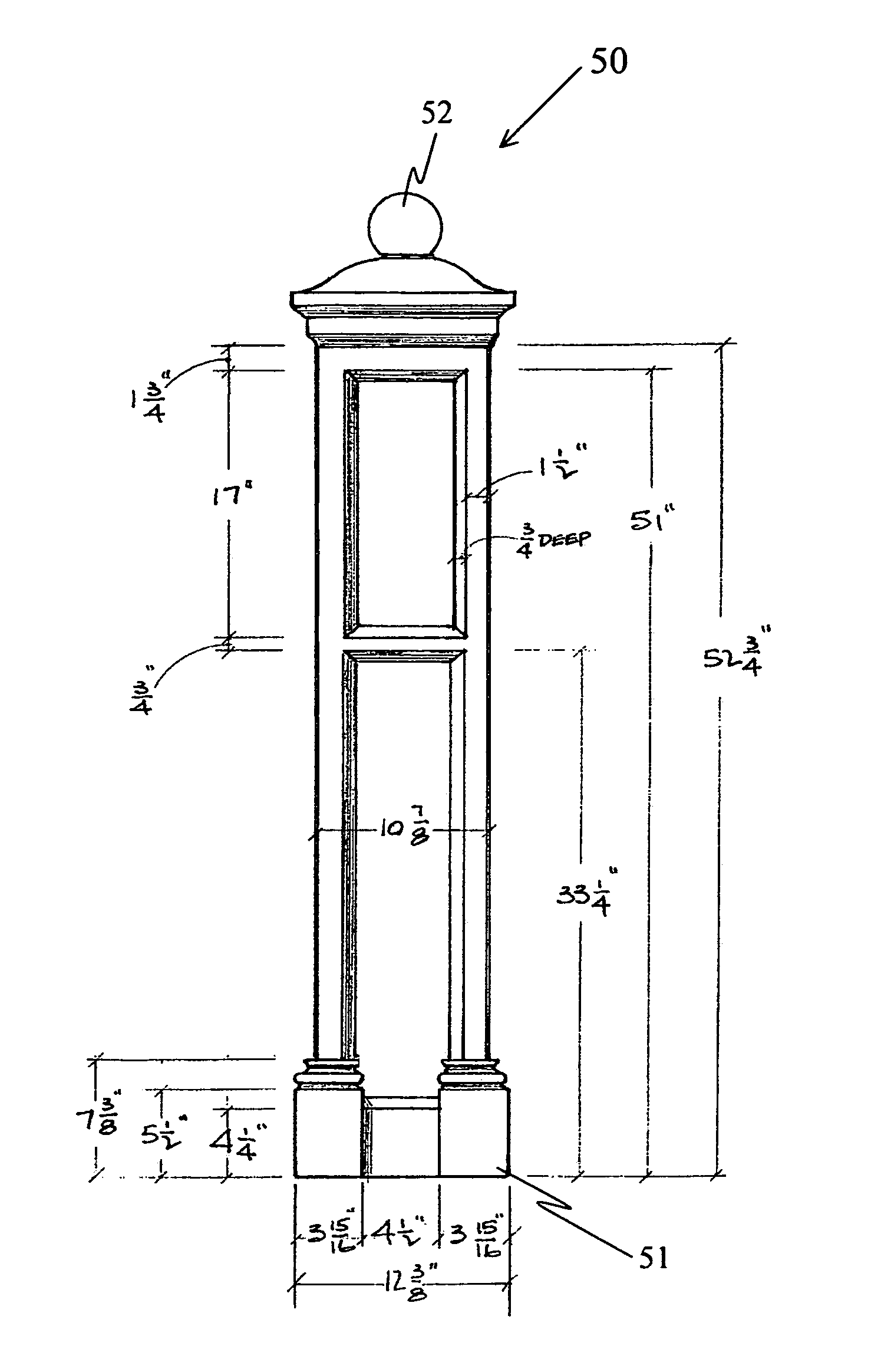
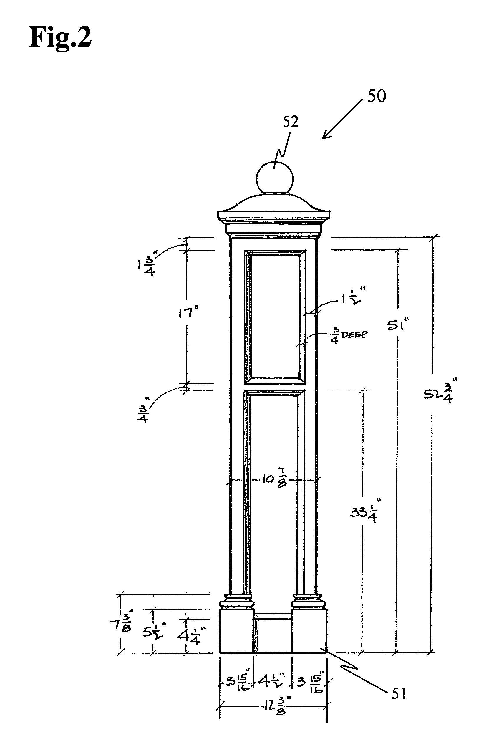
[0035]The present invention provides highly decorative concrete lightweight modular concrete structures such as columns and end cap structures that have intricate designs on the external surfaces, and which are highly resistant to chipping and breakage. This high strength property and smoothness of finish is obtained in part by a layer of short length glass fiber reinforced concrete (GFRC) forming the outer layer of the concrete. The GFRC outer layer is supported by a second layer of GFRC, which uses long length glass fibers so that the columns have a wall thickness of about 0.25 to 0.5 inches. The two-stage glass reinforcement provides the concrete with strength properties that enable the cured hardened columns to be routinely handled by machinery such as forklift trucks or shipped using standard flat bed trucks without chipping of highly decorative column external surfaces, or breakage.

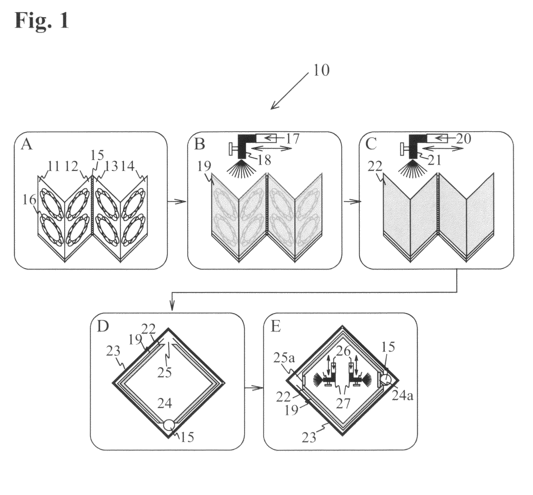
[0036]The process for manufacture of these lightweight, easily transportable decorative GFRC con...


PUM

PropertyMeasurementUnit
lengthaaaaaaaaaa
lengthaaaaaaaaaa
thicknessaaaaaaaaaa

Abstract

Prefabricated, lightweight, modular, concrete structures, such as columns and a variety of end caps, have a strong, chip resistant surface exhibiting ornamental designs that include projections and impressions. The high strength of the surface layer is due to reinforcement of the concrete with alkali resistant short length (0.125-0.25 inch) glass fibers that allow replication of fine surface details in the column surface. The surface layer is supported by a second glass fiber reinforced concrete layer that incorporates long length (0.5-1.5 inch) alkali resistant glass fibers. In combination, the first and second layers are about 0.25 to 0.5 inches thick, and the lightweight column is readily handled by forklift trucks or economically transported on flat bed trucks without surface chipping or breakage. The modular concrete structures include concrete columns, end caps and arches, as well as other geometrically decorative assemblies. They fit into each other and are conveniently and efficiently assembled in the field to form column-like structures that embody a wide variety of geometrical shapes.

Description

BACKGROUND OF THE INVENTION[0001]1. Field of the Invention[0002]The present invention relates to lightweight monolithic concrete structures such as columns with ornamental surfaces having modular end cap elements; and, more particularly to a prefabricated glass fiber reinforced monolithic modular hollow lightweight columns and end caps that can be easily handled and transported.[0003]2. Description of the Prior Art[0004]Processes for the manufacture of concrete structures such as columns are well known in the art. Several of the column casting processes cast heavy solid concrete columns. Hollow round cross-sectional, cylindrical columns have been produced by a few prior art workers. However, these cylindrical columns are devoid of smooth or ornate surface features. Rectangular columns are also produced by prior art processes; but they are not monolithic, since individual faces must be held together by external means.[0005]U.S. Pat. No. 1,936,666 to Hall discloses a form for concrete...

Claims


Application Information

Patent Timeline
Patent Type & Authority Patents(United States)
IPC IPC(8): D04H1/00B32B17/12E04B5/00
CPCB28B7/0044B28B7/0064B28B7/346E04C3/30B28B1/32B28B1/52B28B7/38Y10T428/249924Y10T428/249928Y10T428/249929
Inventor KUDRICK, JEFFREY M
Owner NATURES GATE DESIGNS
Why Eureka
Try Eureka