Integrated optical resonator device for measuring chemical and biological analyte concentrations

Inactive Publication Date: 2010-09-14
FLIR DETECTION
View PDF17 Cites 78 Cited by
  • Summary
  • Abstract
  • Description
  • Claims
  • Application Information

AI Technical Summary

Benefits of technology

[0012]The current invention overcomes the limitations of prior art by providing a method of measuring the binding rate of analytes to a micro-ring sensor by comparing the rate of change in the resonance of the sensor ring to that of a reference ring and relating this to the anal

Problems solved by technology

Although high Q values are advantageous, WGM resonators tend to support a dense optical spectrum of modes which increases the difficulty in tracking the resonant wavelength of one specific mode.
As a result, WGM sensor designs tend to rely on sensing changes in optical intensity related to changes in the cavity Q. Thus, WGM resonators are more susceptible to signal to noise issues relating to small variations in optical intensity due to environmental factors and coupling variations as well as source and detector related intensity noise.
An additional drawback related to the large number of optical modes is that WGM must generally rely on self-referencing.
These measurements can experience error due to

Method used


Image

  • Integrated optical resonator device for measuring chemical and biological analyte concentrations
  • Integrated optical resonator device for measuring chemical and biological analyte concentrations
  • Integrated optical resonator device for measuring chemical and biological analyte concentrations

Examples


Embodiment Construction

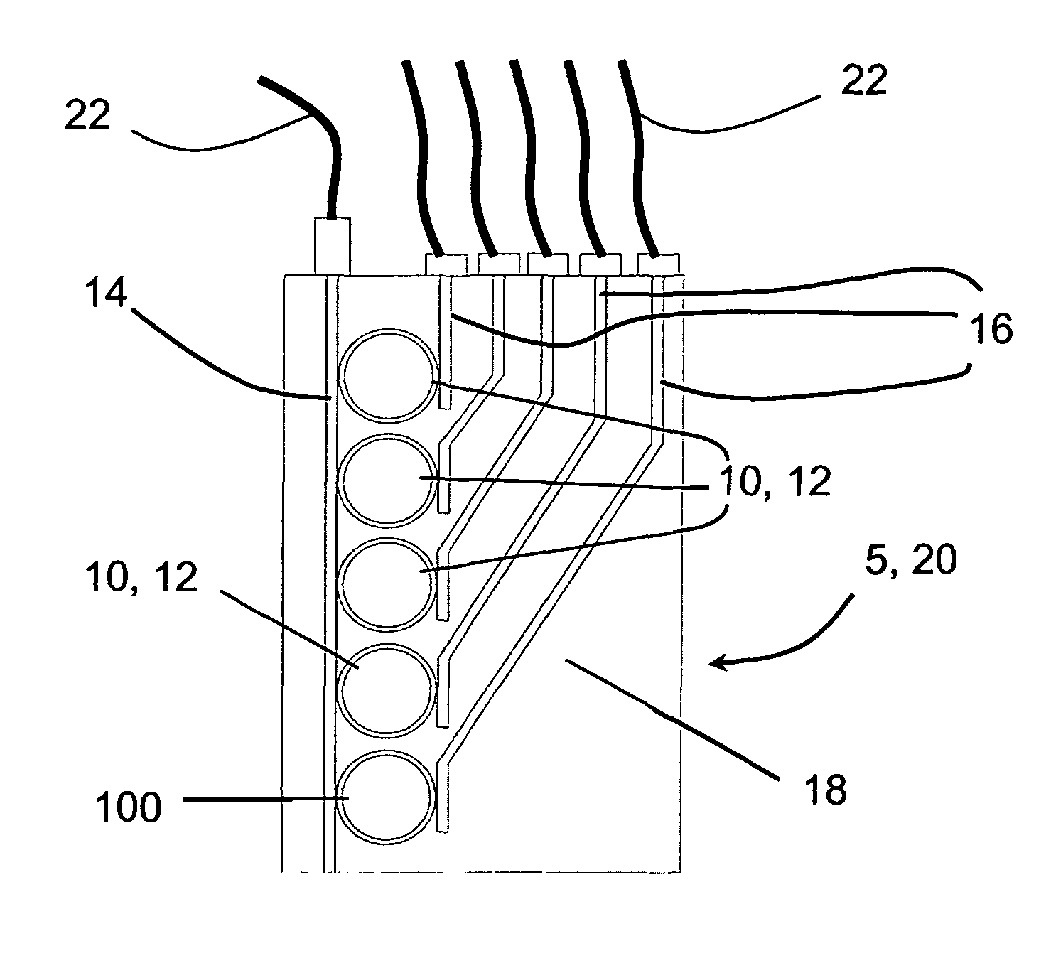
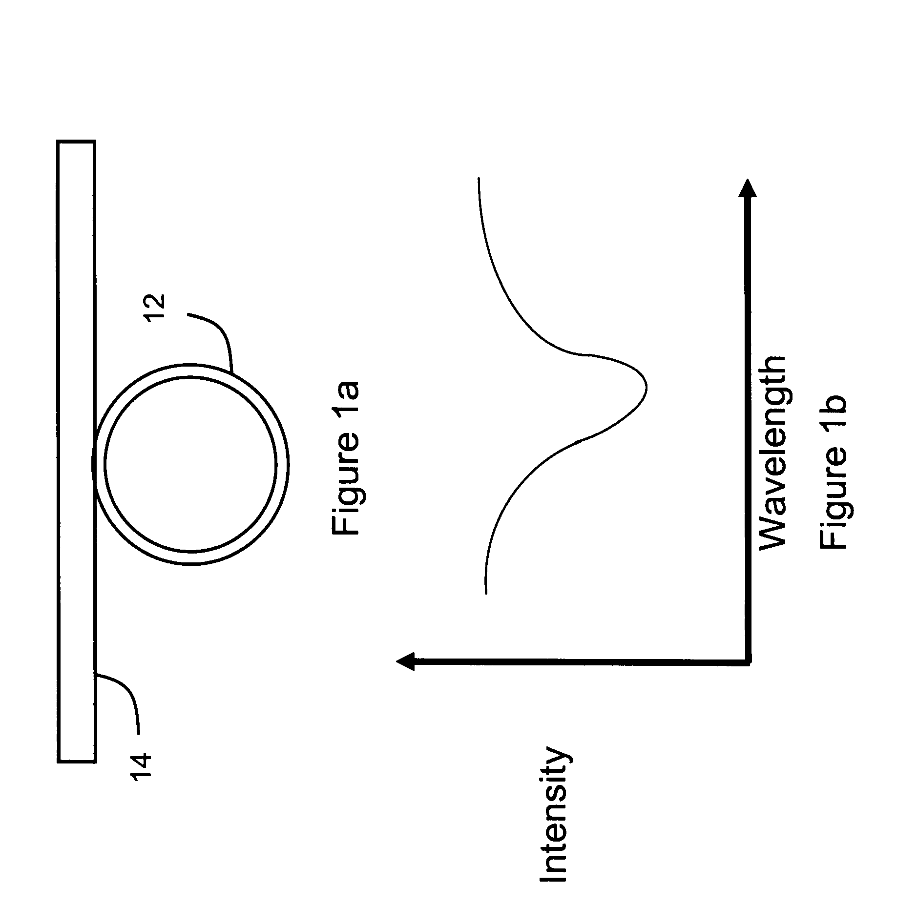
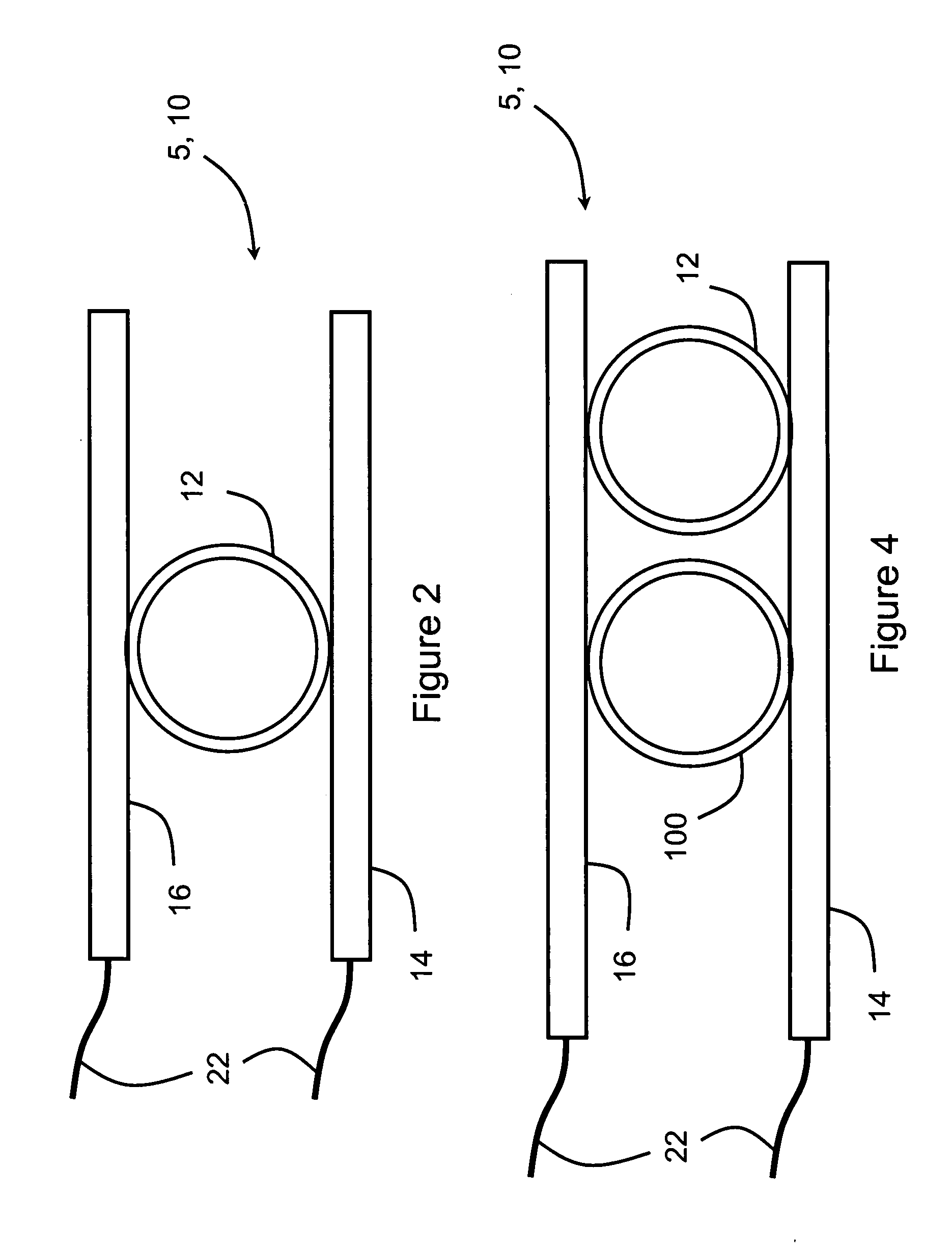
[0023]The current invention utilizes micro-ring resonators to provide real time analysis of trace analytes. A typical micro-ring usually has resolution power of about 7,000˜14,000. The sensing dynamic range of a typical micro-ring resonator, as defined by the free spectrum range, is about 4 nm. As known to those skilled in the art, micro-ring resonators operate based on wave-guiding phenomena specified by boundary conditions. Propagation of light through narrow waveguides generates an evanescent field, a local region of light ‘leakage’, around the surface of the waveguide that extends a distance of 100-300 nm at near infrared wave length. The intensity of the evanescent field decays exponentially as the distance from the surface increases. When the waveguides and micro-rings are precisely aligned and positioned, either vertically or laterally, coupling of their evanescent fields can be achieved. This facilitates certain wavelengths (resonance wavelengths) of light passing through th...


PUM


Abstract

The current invention provides methods for detecting trace analytes in solution or suspension using coupled micro-ring resonators. The methods of the current invention determine the presence and concentration of the target analytes in real time by exposing the micro-ring resonator to the analyte and determining the resulting rate of change of resonance wavelength experienced by a sensing micro-ring resonator as compared to a reference micro-ring resonator.

Description

STATEMENT AS TO FEDERALLY SPONSORED RESEARCH[0001]This application was supported in part by a contract from DARPA Contract #W81XWH-04-C-0139 Subcontract 70030-NOM. The United States Government may have rights in and to this application by virtue of this funding.BACKGROUND[0002]A number of platforms have been developed for chemical and biological sensing including optical techniques such as infra-red absorption, surface plasmon resonance (SPR) sensors, florescence-based sensors, and several methods employing optical resonators. These optical resonator sensor designs are attractive solutions as they tend to have a small form factor and can be designed with high sensitivities. Optical resonator sensor platforms can be categorized into two groups: multimode whispering gallery devices and single mode waveguide resonator devices.[0003]Whispering gallery mode (WGM) devices tend to focus on changes in optical absorption and the effect on the resonator quality factor. These devices have been...

Claims


Application Information

Patent Timeline
IPC IPC(8): G01N21/00
CPCG01N21/7746G01N33/54373G01N33/54393
Inventor WANG, SHAOPENGRAMACHANDRAN, AKHILESHKNOBBE, EDWARD TJOHNSON, FREDERICK GORRLITTLE, BRENT EVERETTGOAD, DAVID WESLEY
Owner FLIR DETECTION
Why Eureka
Try Eureka