LLC converter synchronous FET controller and method of operation thereof

a technology of synchronous fet controller and llc converter, which is applied in the direction of electric variable regulation, process and machine control, instruments, etc., can solve the problems of substantial “body diode conduction loss” and certain drawbacks of llc converter employment, and achieve the effect of lessening the duration of the conduction tim

Active Publication Date: 2010-09-14
ACLEAP POWER INC
View PDF4 Cites 15 Cited by
  • Summary
  • Abstract
  • Description
  • Claims
  • Application Information

AI Technical Summary

Benefits of technology

[0005]To address the above-discussed deficiencies of the prior art, one aspect of the invention provides a synchronous field effect transistor (FET) power controller, including a first rectifying FET. This aspect further provides a first driver coupled to the first rectifying FET. The first driver is configured to both: (a) activate the first rectifying FET if the first driver senses an activation body diode conduction current of the first rectifying FET and (b) deactivate the first rectifying FET if the first driver receives a first deactivation signal. This aspect further provides a first primary FET that is deactivated by a delay of the first deactivation signal. In this aspect, the delay lessens duration of a conduction time of a deactivation body diode conduction current of the first rectifying FET.

Problems solved by technology

However, there are certain drawbacks in employment of conventional LLC converters.
These drawbacks can include a substantial “body diode conduction loss” of various transistors during a rectification cycle.

Method used


Image

  • LLC converter synchronous FET controller and method of operation thereof
  • LLC converter synchronous FET controller and method of operation thereof
  • LLC converter synchronous FET controller and method of operation thereof

Examples


Embodiment Construction

[0014]Generally, the present disclosure recognizes that it is advantageous to control and limit forward body diode conduction in an LLC converter. Unlike conventional LLC converters, which generally relied upon “worst case” tolerance design to control timing of synchronization of primary and secondary (“rectifying”) transistors, the application employs timed switching sequences to turn on and off the various synchronizing transistors.

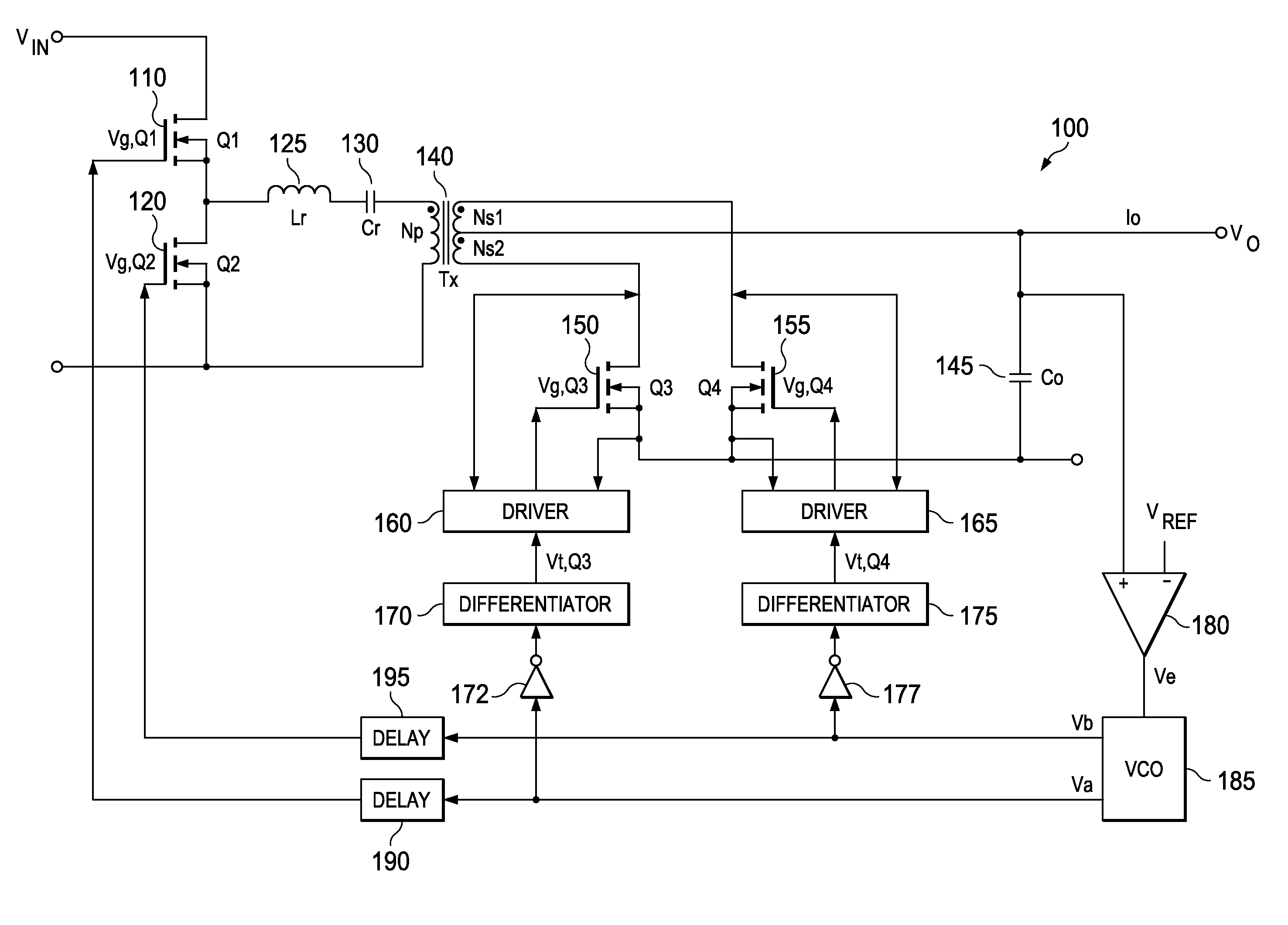
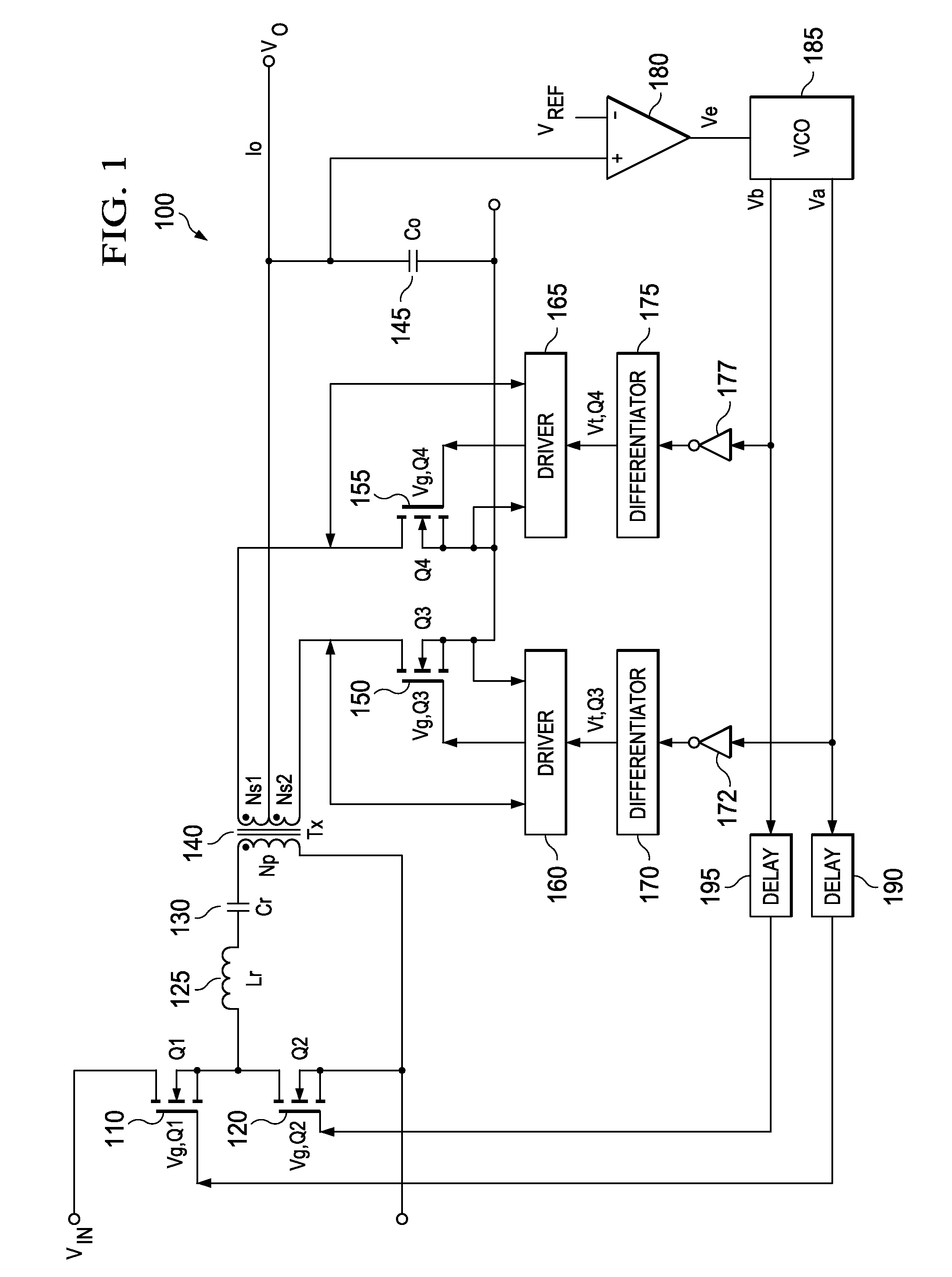
[0015]Referring initially to FIG. 1, illustrated is an embodiment of an LLC converter 100 (“LLC 100”) constructed according to the principles of the invention. First, a description of the overall construction of the LLC converter 100 will be given. Then, a description of its operation will be given regarding timing diagrams FIGS. 3A and 3B.

[0016]In the LLC 100, a voltage input “Vin” can be applied across a source of a first primary (“Q1”) FET, such as metal-oxide-semiconductor field-effect transistor (“MOSFET”) 110 and a drain of a second primary FET, s...


PUM


Abstract

A method for operating a power controller is provided. The method includes activating a rectifying FET upon a detection of an activation body diode conduction current occurring in the rectifying FET. The method generates an activation signal for a corresponding primary FET. The method further includes deactivating the corresponding rectifying FET upon a reception of a deactivation signal. The method further includes then deactivating the corresponding primary FET after delaying the deactivation signal, wherein the delay lessens a conduction time of a deactivation body current of the corresponding rectifying FET. The method further includes generating a deactivation signal and deactivating the corresponding rectifying FET upon a reception of the deactivation signal and deactivating the primary FET after delaying the deactivation signal. The delaying lessens a conduction time of a deactivation body current of the corresponding rectifying FET.

Description

TECHNICAL FIELD OF THE INVENTION[0001]The invention is directed, in general, to a synchronous power converter and, more specifically, to a timing of a rectification of a secondary side of the synchronous power converter.BACKGROUND OF THE INVENTION[0002]Synchronous power converters are an ever-increasingly important part of power conversion strategies and systems. One type of power converter that has been of increasing interest is the “inductor inductor capacitor” converter (“LLC converter”), due to various advantages associated therewith. For example, please see Yang, “Topology Investigation for Front End DC / DC Power Conversion for Distributed Power System,” Virginia Polytechnic Institute and State University, 2003, incorporated herein by reference in its entirety.[0003]However, there are certain drawbacks in employment of conventional LLC converters. These drawbacks can include a substantial “body diode conduction loss” of various transistors during a rectification cycle. For examp...

Claims


Application Information

Patent Timeline
Patent Type & Authority Patents(United States)
IPC IPC(8): H02M3/335H02M7/217
CPCH02M3/33592Y02B70/1491H02M2001/0058Y02B70/1475H02M1/0058Y02B70/10
Inventor REDDY, RAGHOTHAMA
Owner ACLEAP POWER INC
Why Eureka
Try Eureka