Ballistic/impact resistant foamed composites and method for their manufacture

a composite material and foam technology, applied in the field of composite armor systems, can solve the problems of not having the required severe impact (ballistic) and flame resistance properties for many military applications, and their densities are generally too high for applications that require mobility, ground, sea or air, and achieve the effect of light weigh

Inactive Publication Date: 2010-09-21
TAN SENG
View PDF1 Cites 34 Cited by
  • Summary
  • Abstract
  • Description
  • Claims
  • Application Information

AI Technical Summary

Benefits of technology

[0013]It is therefore apparent that there exists a continuing need for lightweight and improved armor systems for land vehicular, individual ...

Problems solved by technology

Metals and ceramics are recognized to have good ballistic properties, but their densities are generally too high for applications that require mobility, ground, sea or air.
Similarly, conventional polymeric foam cored sandwich structures are designed to enhance the bending stiffness of structures, but generally do not exhibit satisfactory ballistics resisance.
Although such current foamed structures may have adequate impact properties for some applications, they do not have the required severe impact (ballistic) and flame resistant properties required for many military applications.
However, the densities of these materials are normally too high for many applications including aircraft and portable protective shields.
These structures are so heavy that they require several soldiers to move them.
Anything this heavy cannot posses a mobility that is satisfactory for use in combat.
However, metallic and ceramic armor systems are both too heavy for personal protective shields that require mobility.
However, even given the lightweight of the constituent materials they are generally...

Method used


Image

  • Ballistic/impact resistant foamed composites and method for their manufacture
  • Ballistic/impact resistant foamed composites and method for their manufacture
  • Ballistic/impact resistant foamed composites and method for their manufacture

Examples


example 1

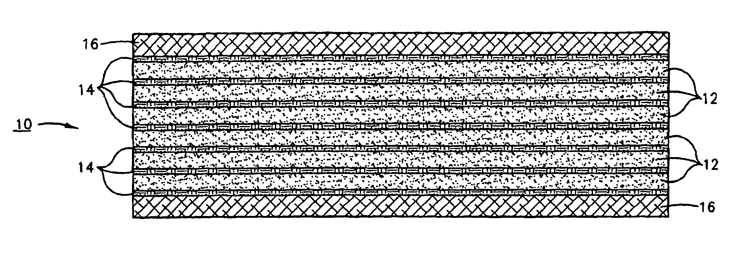
[0041]Xydar® SRT900 (LCP) powders were obtained from Amoco (4500 McGinnis Ferry Rd., Alpharetta, Ga. 30202). Kevlar® and Zylon® (PBO) fabrics were purchased from Barrday, Inc. (75 Moorefield St., P.O. Box 790, Cambridge, ON N1R 5W6) and Hexcel Schwebel (2200 South Murray Ave., Anderson, S.C.). Five pieces of PBO fabric about 12 by 12-in were cut. The Zylon®fabrics were laid in a steel mold and Xydar® powders spread between adjacent layers of Zylon® fabrics. The mold was then closed and heated up under clamping pressure to about 320° C. for about 30-min. After cooling to ambient a consolidated panel was obtained. The consolidated panel was foamed using a pressure vessel at a foaming temperature of about 370° C. under nitrogen gas at about 3000 psi in accordance with the practice of U.S. Pat. No. 6,232,354 which is incorporated herein by reference in its entirety. After holding the temperature for a short period of time the gas was vented quickly and the sample removed from the mold. ...

example 2

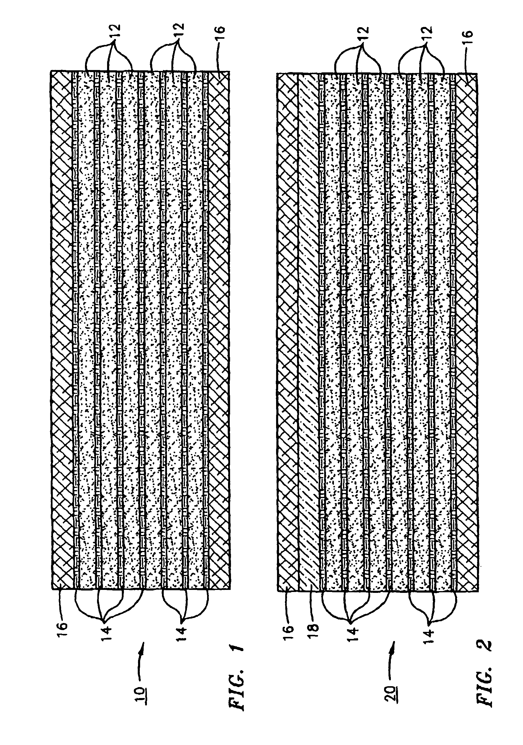
[0042]Ultem® (polyetherimide) powders obtained from GE Plastics (One Plastics Ave, Pittsfield, Mass. 01201) and graphite / fabrics obtained from BFG Industries, Inc. (90 Huger Street, Cheraw, S.C. 29520) were molded into composite panels, 12 by 12-in, using 5 to 19 layers of Kevlar® or Zylon® (PBO) fabrics with Ultem powders between adjacent layers of fabric by treatment at about 325° C. under elevated pressure. Additional panels also containing 4 layers of graphite fabric, 2 near the bottom surface and 2 near the upper surface were also molded. The composite panels were foamed using a pressure vessel at about 300˜325° C. with nitrogen as the foaming gas, at pressures between about 1500˜5000 psi. After holding at temperature for about 20 minutes, the gas was vented and a foamed composite panel obtained. The foamed composite panel was sawed into cubical shapes for compression testing. Cross-sectional views show that these foamed composites have a very uniform structure. The results of ...

example 3

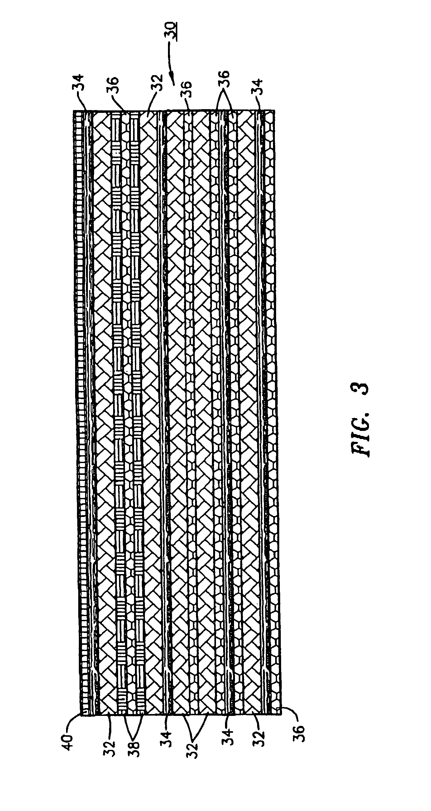
[0043]Phenolic coated Kevlar® fabrics and phenolic coated Zylon® containing less than 20% by weight of phenolic were obtained from Barrday Inc. and, Hysol® EA 9696 film and paste adhesives were obtained from Loctite Aerospace (2850 Willow Pass Road, P.O. Box 312, Bay Point, Calif. 94565). Facesheets were fabricated using 24 plies of Kevlar® 745 bonded with the Hysol® adhesives. These facesheets weighed about 2.5-lb and were 0.44-in thick. Compression molded panels 12.25 by 12.25-in were fabricated with these facesheets in accordance with the process described in Example 2. The thickness and weight of these panels were about 0.32-in and 1.79 lb. Similar panels were also fabricated using 20-25-layer of Zylon® fabrics. A panel with 25 plies of phenolic coated Zylon® weighed about 1.18 LB and measured about 0.203-in thick. Two facesheets and a foamed core were bonded together using either 2 layers of film adhesive or some paste adhesive, EA9696, between each interface. They were then cu...


PUM

PropertyMeasurementUnit
Pore sizeaaaaaaaaaa
Temperatureaaaaaaaaaa
Pressureaaaaaaaaaa

Abstract

A foamed composite armor laminate comprising interleaved combinations of ballistic resistant fabrics, and ceramic and/or metallic plates or sheets in a polymeric foam matrix. The foamed composite armor can be fabricated by inserting polymer powder or sheets between layers of fabric and/or ceramic or metallic sheets to form a laminated structure, heating this laminated structure under pressure to form a consolidated panel, and then foaming the polymeric portion of the consolidated panel in an autoclave or pressure vessel by saturating the polymeric portion with inert gas at elevated temperature, rapidly releasing the pressure and controllably cooling the laminated structure to ambient. Alternatively, pre-foamed panels can be laminated to fabric, ceramic and/or metallic sheets using adhesives or the like. Through proper selection of the various elements of the laminate, i.e. the foamed polymer matrix, the polymeric fabric(s) and the ceramic and metallic sheet(s), a wide variety of ballistic, flame retardance, stiffness and other properties can be custom designed into the product for specific end use applications.

Description

[0001]This application is a continuation-in-part of U.S. patent application Ser. No. 10 / 982,215 filed Nov. 5, 2004 now abandoned.[0002]The United States of America may have certain rights in this application under the terms of Contracts Nos. F33615-03-M-5033 and F33615-03-C-3321 from Wright Patterson Air Force Base.FIELD OF THE INVENTION[0003]The present invention relates to composite armor systems and more particularly to foamed composites comprising layered or laminated combinations of fabrics, fibers, ceramic and / or metallic plates in a polymeric foam matrix.BACKGROUND OF THE INVENTION[0004]Fiber reinforced composites have many applications in fields that require lightweight structure, fuel efficiency, and environmental durability in both the military and civilian sectors. In addition to the need for flame and moisture resistance, many military applications require that the materials have impact and ballistic resistant properties. Metals and ceramics are recognized to have good b...

Claims


Application Information

Patent Timeline
IPC IPC(8): B32B5/24B32B3/26
CPCB32B5/22B32B5/26B32B5/32B32B15/08F41H5/0428F41H5/0457Y10S428/911Y10T442/647Y10T428/249987Y10T442/335Y10T442/649Y10T442/3325Y10T442/651Y10T442/3423Y10T442/654Y10T428/249982Y10T442/656Y10T428/249976Y10T428/249953Y10T428/24996Y10T442/3341Y10T442/3431Y10T442/3382Y10T428/249977
Inventor TAN, SENG
Owner TAN SENG
Why Eureka
Try Eureka