Method for the detection of the rotational position of the rotor of a DC motor with commutator

a technology of dc motor and commutator, which is applied in the direction of dynamo-electric machines, dc motor rotation control, electric/magnetic devices, etc., can solve the problem of insufficient reliability of current ripple detection

Active Publication Date: 2010-09-21
BEHR HELLA THERMOCONTROL
View PDF17 Cites 16 Cited by
  • Summary
  • Abstract
  • Description
  • Claims
  • Application Information

AI Technical Summary

Benefits of technology

[0022]According to an advantageous variant of the invention, it is provided that, after a logic pulse has been generated in the logic signal, the next logic pulse will be generated only when, after a lapse of time of e.g. half the period of waviness of the rotor current signal, the output signal of at least one of the detector units includes a pulse. In this variant of the invention, the generating of a logic signal is suppressed for half the period of the rotor current signal. In this manner, it is reliably prevented that, erroneously, two pulses per period of the rotor current signal are generated in the logic signal or that pulses are included in the count which have been erroneously generated, e.g. due to disturbances of the rotor current signal.

Problems solved by technology

In known ripple count methods, a problem resides in the existence of load conditions and idle conditions of the DC current motor during which the detection of the current ripple is not performed with sufficient reliability.
Further, depending on the respective use of a DC motor with commutator (DC motor with asymmetrical or symmetrical motor), it may happen that individual ripples are generated which, if they were included in the counting, would cause a faulty result.

Method used


Image

  • Method for the detection of the rotational position of the rotor of a DC motor with commutator
  • Method for the detection of the rotational position of the rotor of a DC motor with commutator

Examples


Embodiment Construction

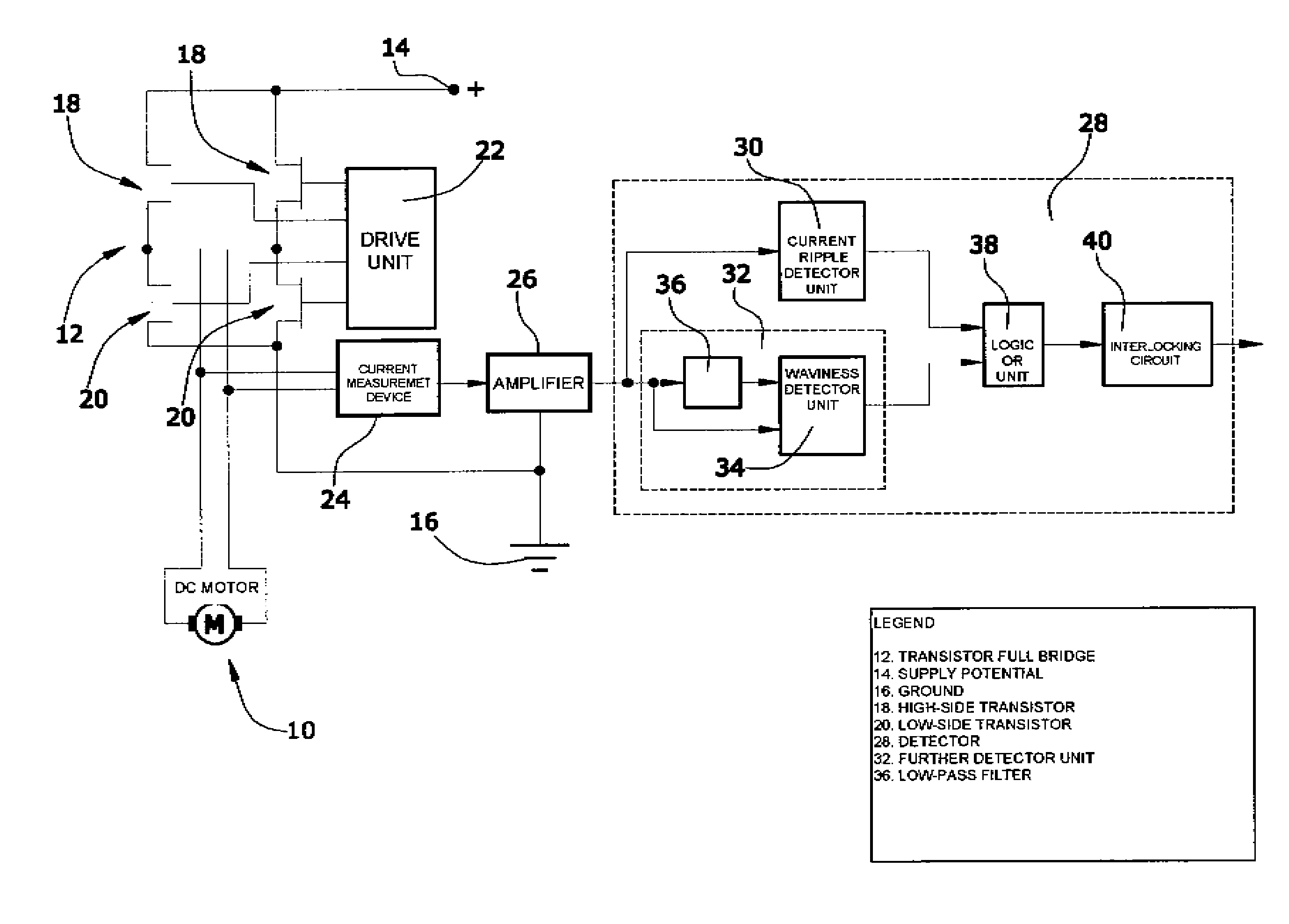
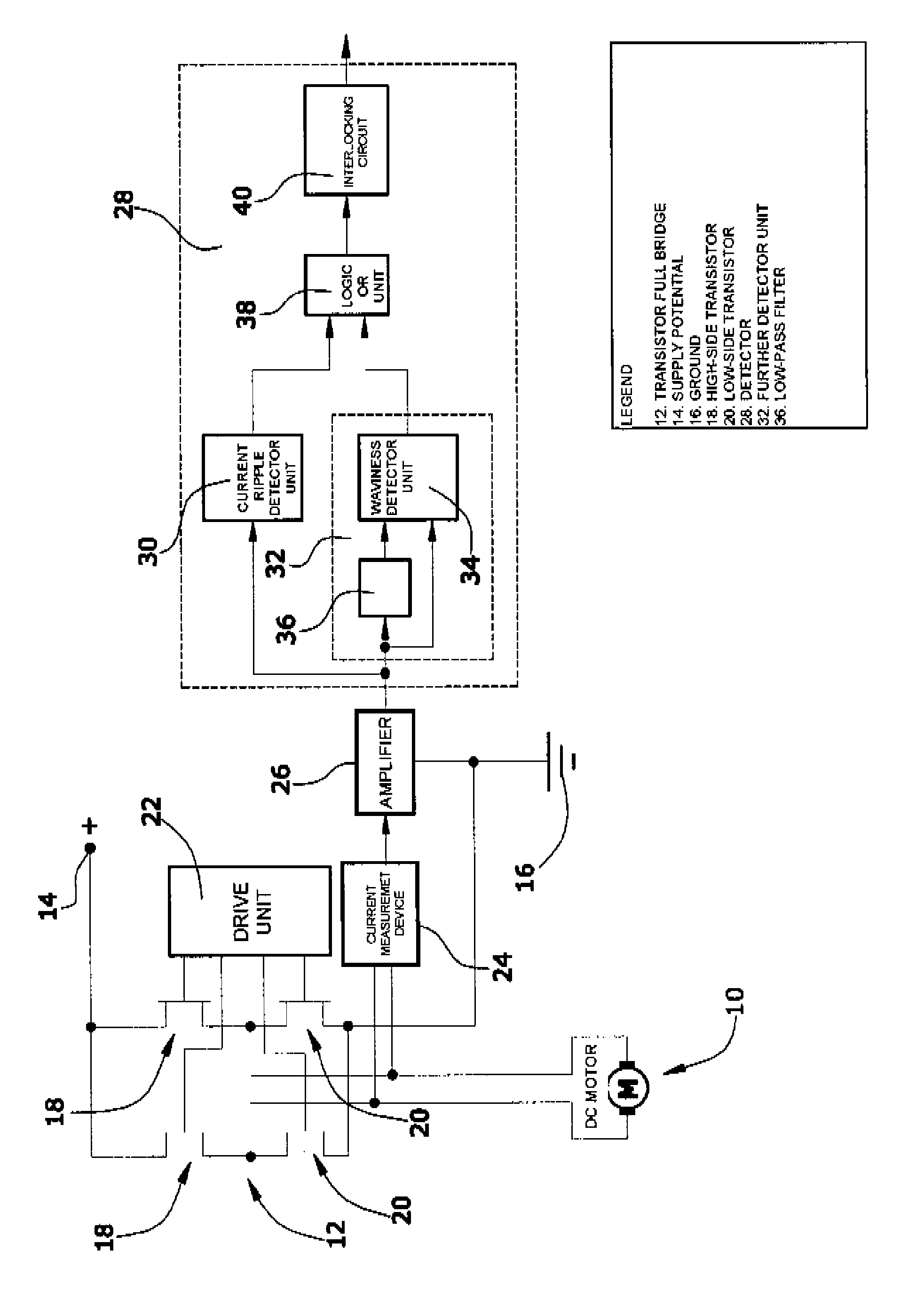
[0030]As schematically illustrated in the drawing, a DC motor 10 with commutation, in which motor the development of the rotor current signal is to be examined, is driven by a transistor full bridge 12. This transistor full bridge 12 is connected between a supply potential 14 and the ground 16 and comprises two high-side transistors 18 and two low-side transistors 20. All of the transistors 18,20 are driven by a drive unit 22. The DC motor 10 which is to be examined is arranged in the bridge branch of transistor full bridge 12. The rotor current of DC motor 10 is picked up for measurement by a current measurement device 24 so that the development of the rotor current signal can be observed through measurement technology. In the present embodiment, the current measurement is performed by resistance measurement of the RSD-ON resistance of the respective current-carrying low-side transistor 20.

[0031]The output signal of the current measurement device 24 is amplified in an amplifier 26 ...


PUM


Abstract

In a method for the detection of the rotational position of the rotor of a DC motor with commutator by evaluating the time development of a rotor current signal of the DC motor, said signal comprising a periodic waviness around an average value and comprising current ripples generated by commutation which are superimposed to said waviness, the rotor current signal of a current ripple detector unit (30) is supplied for detecting the current ripples of the rotor current signal. The rotor current signal is further supplied to a waviness detector unit (34) for detecting a half or full wave of the rotor current signal. The current ripple detector unit (30) is arranged to output a current ripple pulse for each detected current ripple. The waviness detector unit (34) is arranged to output a waviness pulse for each period of the waviness. The output signals of both detector units (30,34) are supplied to a logic OR unit (38) for generating a logic signal. Within a period of the rotor current signal, at least one of the detector units (30,34) will output a pulse. Thereby, the logic signal comprises a logic pulse for each period of the rotor current signal.

Description

RELATED FOREIGN APPLICATION[0001]The present application claims the priority of German Patent Application DE 10 2006 044 070.6, the disclosure of which is herewith incorporated herein by reference.BACKGROUND OF THE INVENTION[0002]The present invention relates to a method for the detection of the rotational position of the rotor of a DC motor with commutator by evaluating the time development of a rotor current signal of the DC motor, which signal comprises a periodic waviness around an average value, and current ripples generated by commutation which are superimposed to said waviness. Such a method can be applied e.g. in actuating systems in order to detect, without using a sensor, the present moving position of an actuator driven by the DC motor. The method is particularly useful in automobiles, notably for automatic window lifts, electrically adjustable seats, a throttle valve in the internal combustion engine, as well as mixing valves and air-distribution valves, respectively, of...

Claims


Application Information

Patent Timeline
Patent Type & Authority Patents(United States)
IPC IPC(8): H02K27/00H02P25/10H02P3/18H02P1/24
CPCG01P3/48H02P7/0044H02P7/0094H02P7/04
Inventor KNITTEL, OTTOKRIENER, MICHAEL
Owner BEHR HELLA THERMOCONTROL
Why Eureka
Try Eureka