Laser-based coordinate measuring device and laser-based method for measuring coordinates

a laser-based, coordinate-based technology, applied in distance measurement, instruments, surveying and navigation, etc., can solve the problems of affecting the accuracy of laser beams, etc., to achieve improved laser beam steering, low cost, and easy manufacturing

Active Publication Date: 2010-09-21
FARO TECH INC
View PDF41 Cites 393 Cited by
  • Summary
  • Abstract
  • Description
  • Claims
  • Application Information

AI Technical Summary

Benefits of technology

[0010]An object of the present invention is to provide a laser-based coordinate measuring device with improved laser beam steering, six degree of freedom measurements, and capability to locate multiple retroreflectors dist

Problems solved by technology

However, such six degree-of-freedom systems, whether or not they are employing laser techniques, are generally inaccurate, slow, limited in radial or angular range, and/or expensive.
These optical elements and their mounts are costly.
Also, they are subject to tilting and bending as a result of ther

Method used


Image

  • Laser-based coordinate measuring device and laser-based method for measuring coordinates
  • Laser-based coordinate measuring device and laser-based method for measuring coordinates
  • Laser-based coordinate measuring device and laser-based method for measuring coordinates

Examples


second embodiment

[0092]The second embodiment of the invention is generally similar to that shown in FIG. 1 except for the probe assembly 180 is replaced by probe assembly 1780, as shown in FIG. 17. Probe assembly 1780 contains a single small retroreflector 1708 to the side of retroreflector 107. Retroreflector 1708 is approximately aligned with the first line of intersection. At the start of the measurement, the photosensitive array 725 of FIG. 7 displays a pattern similar to that of FIG. 12, with the details of the pattern dependant on the pitch, yaw, and roll angles of retroreflector 107. As explained previously, at the start of the measurement, it is not possible to tell which line segments correspond to each of the three lines of intersection. To resolve this ambiguity, the tracker performs a search in which it directs laser beam 153 in succession to each of the six possible locations of retroreflector 1708. A flash of light on position detector 341 of FIG. 3 indicates that the first line of int...

third embodiment

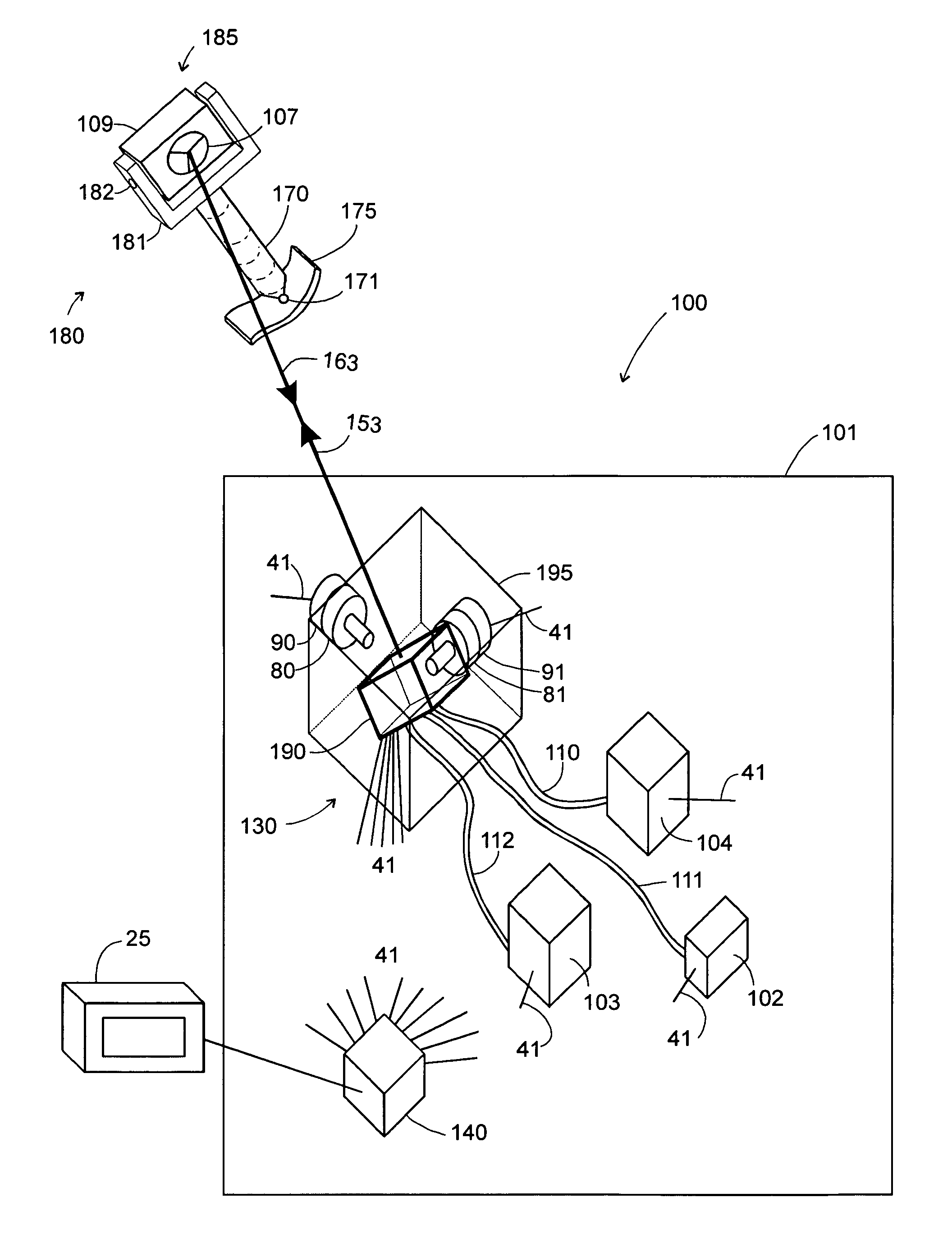
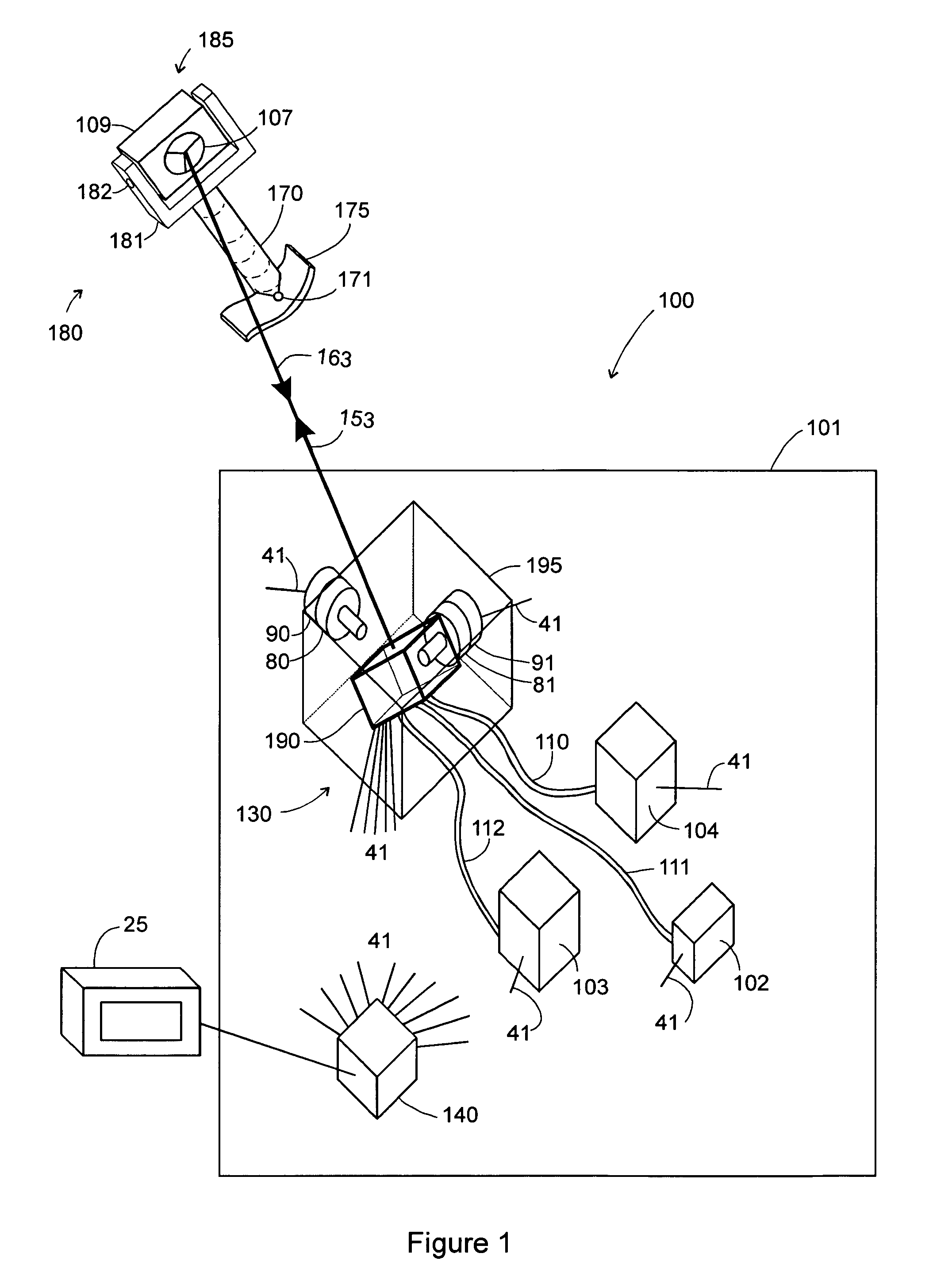
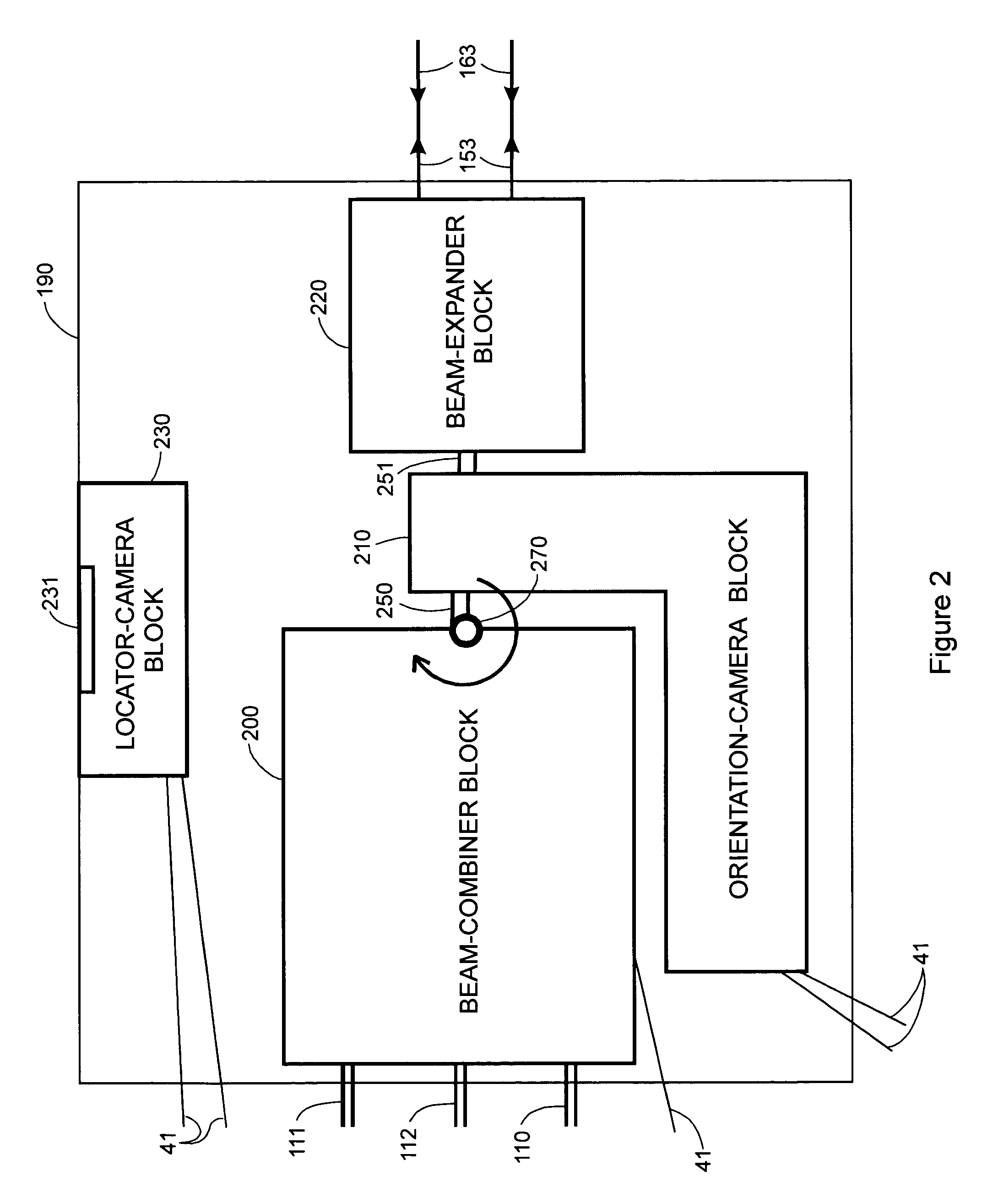
[0095]The third embodiment of the invention provides a laser tracker 1800 as shown in FIG. 18 that uses a steering reflector 1804 within gimbal mount 95 to direct laser beam 1853 to retroreflector 107. Laser 1802 emits laser light that is sent to retroreflector 107. Optical block 1806 contains beam expander 220 and any other optical beam-conditioning elements that may be required. Laser light returning from retroreflector 107 is sent to distance-measuring device 1814, which may be either an absolute-distance meter or an incremental-distance meter. Part of the returning laser light is also reflected off beam splitter 1809 to position detector 341. The beam splitter 701 reflects a portion of laser beam 54 into orientation-camera subsystem 1810. Orientation camera subsystem 1810 comprises afocal lens block 710 and relay / array block 720, also shown in FIG. 7. The optical elements within blocks 1806 and 1810 of FIG. 18 are substantially equivalent to the optical elements within blocks 22...


PUM


Abstract

A laser based coordinate measuring device measures a position of a remote target. The laser based coordinate measuring device includes a stationary portion, a rotatable portion, and at least a first optical fiber. The stationary portion has at least a first laser radiation source and at least a first optical detector, and the rotatable portion is rotatable with respect to the stationary portion. The first optical fiber system, which optically interconnects the first laser radiation source and the first optical detector with an emission end of the first optical fiber system, has the emission end disposed on the rotatable portion. The emission end emits laser radiation to the remote target and receives laser radiation reflected from the remote target with the emission direction of the laser radiation being controlled according to the rotation of the rotatable portion.

Description

[0001]The present application claims the benefit of U.S. Patent Application Nos. 60 / 145,315 filed Jul. 23, 1999, 60 / 145,686 filed Jul. 26, 1999, and 60 / 171,474 filed Dec. 22, 1999, which are hereby incorporated by reference. The present application also hereby incorporates by reference U.S. patent application Ser. No. 09 / 285,654 filed Apr. 5, 1999.BACKGROUND OF THE INVENTION[0002]1. Field of the Invention[0003]The present invention relates to a coordinate measuring device and, more particularly, to a laser based coordinate measuring device.[0004]2. Discussion of the Related Art[0005]There is a class of instrument that measures the coordinates of a point by sending a laser beam to a retroreflector target that is in contact with the point. The instrument determines coordinates by measuring the distance and the two angles to the retroreflector target. There is another class of instrument that is capable of measuring the three orientation angles (pitch, yaw, and roll) of a retroreflecto...

Claims


Application Information

Patent Timeline
IPC IPC(8): G01B9/02
CPCG01B11/002G01B11/026G01S17/66G01S5/163G01B11/03G01B9/02012G01C3/08G01S17/42G01B11/02
Inventor BRIDGES, ROBERT E.BROWN, LAWRENCE B.WEST, JAMES K.ACKERSON, D. SCOTT
Owner FARO TECH INC
Why Eureka
Try Eureka