Feedback control device for photo-colorimetric parameters for a light box with color LEDs

Inactive Publication Date: 2010-09-28
THALES SA
View PDF18 Cites 15 Cited by
  • Summary
  • Abstract
  • Description
  • Claims
  • Application Information

AI Technical Summary

Problems solved by technology

However, the use of CCFL tubes has many drawbacks:they require a high supply voltage, which may be up to 2000 volts AC.
The main consequences of this are:the use of specific coiled components, these being bulky, heavy, expensive and not very reliable,the use of specific printed and wiring circuits which increase the cost and the production time,the use of complex assembling and finishing technologies, necessary for ensuring correct operation even in the event of depressurization, high humidity or thermal shock,the risk of electric arcs (with smoke generation) in the event of component failure andthe emission of substantial electromagnetic radiation difficult to control insofar as radiation is by nature emitting at the front face of the displays;they have a limited luminance dynamic range.
The performance of the fluorescent lamps is degraded due to the following phenomena:depletion of vaporized gas (mercury vapor),reduction in the emissive power of the electrodes,opacification of the glass of the fluorescent tube andloss of efficiency of the phosphors coating the inside of the tube, which behave differently and change the color of the light emitted;their photometric efficiency at low temperature is poor and cold starts reduce their lifetime;poor performance of the fluorescent tubes when started up after being off for a long time (delay in the first light appearing, followed by chaotic operation);the ends of the fluorescent tubes, which do not emit light, are quite long, often more than one centimeter;they are relatively fragile due to their material (glass tube) combined with a small diameter (around 2 millimeters) and to long length, which may exceed 200 millimeters;it is tricky to fix them, requiring mechanical retention and electrical insulation;their poor thermal control due to a little heat dissipation drained away by conduction through the structure, heat being removed only by natural convention; andthe risk of obsolescence of these very specific components, which are difficult to replace.
However, until recently their use was limited insofar as the photometric efficiency of LEDs, that is to say the percentage of electrical energy converted effectively into light energy, remained quite poor and considerably lower than that of fluorescent tubes.
Secondly, the emitted luminance substantially decreases with operating time.
Thirdly, the red component of the light emitted is generally quite weak.
These variations in efficiency result in variations in calorimetric response that are not easily controllable.
This is because the calorimetric response obtained is more satisfactory and its variations with the operating time are more limited.
However, the luminance efficiency is not satisfactory and this type of component remains marginal in the LED market, thereby posing long-term supply or obsolescence problems.
However, these technologies, which are complex to implement, remain marginal.
The technological process for manufacturing the various types of LED does not, however, guarantee perfect reproducibility of the photometric and colorimetric characteristics.
However, this solution has a major drawback.
However, the measurement devices necessarily disturb the proper operation of the LB.
This is because either these devices are located in the useful area of the lighting unit and introduce calorimetric response and luminance nonuniformities, or these devices are located outside the useful area of the lighting unit, but in this case the lighting unit is larger than that of the optical valve, thus increasing the final size of the display.

Method used


Image

  • Feedback control device for photo-colorimetric parameters for a light box with color LEDs
  • Feedback control device for photo-colorimetric parameters for a light box with color LEDs
  • Feedback control device for photo-colorimetric parameters for a light box with color LEDs

Examples


Embodiment Construction

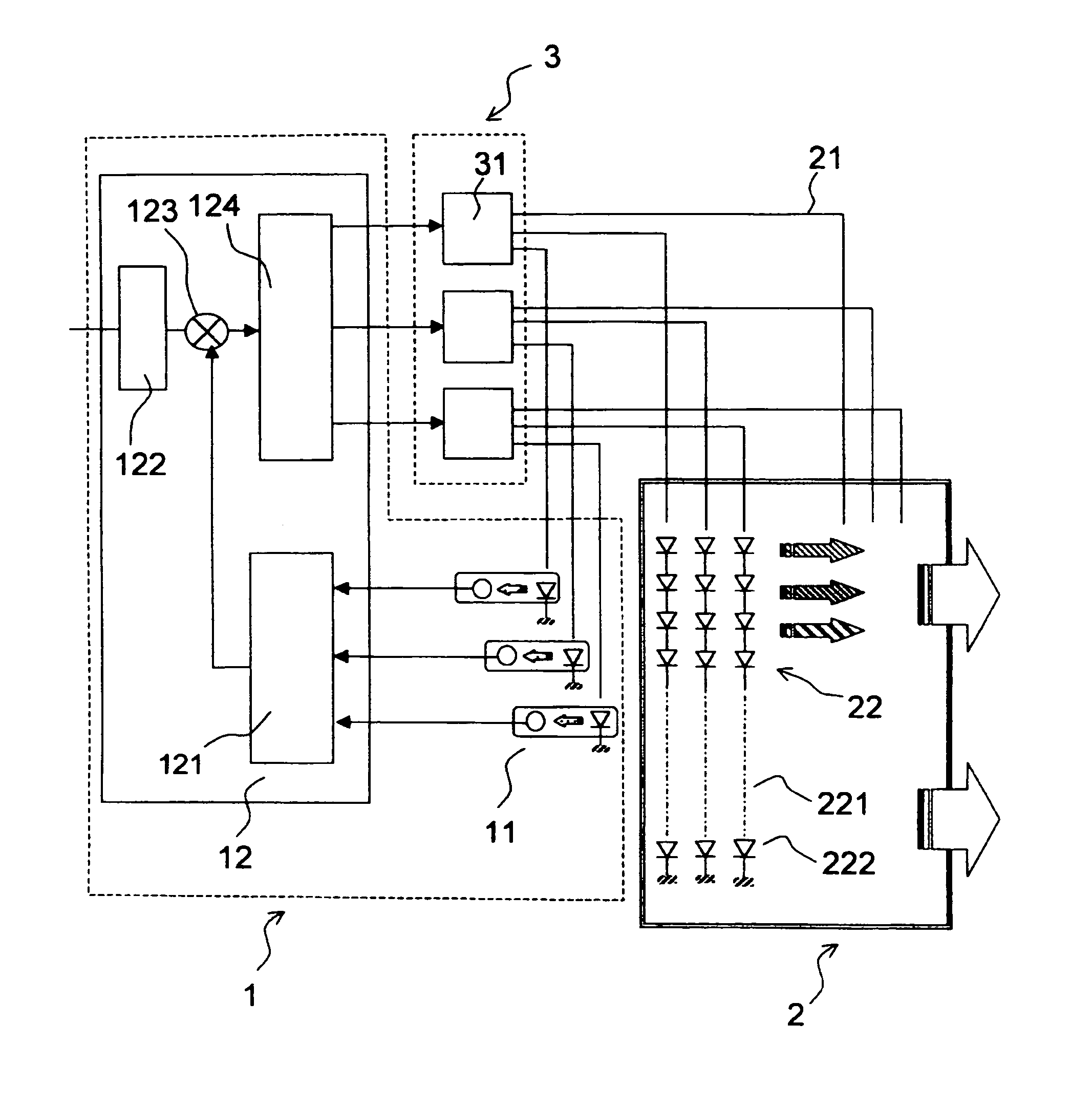
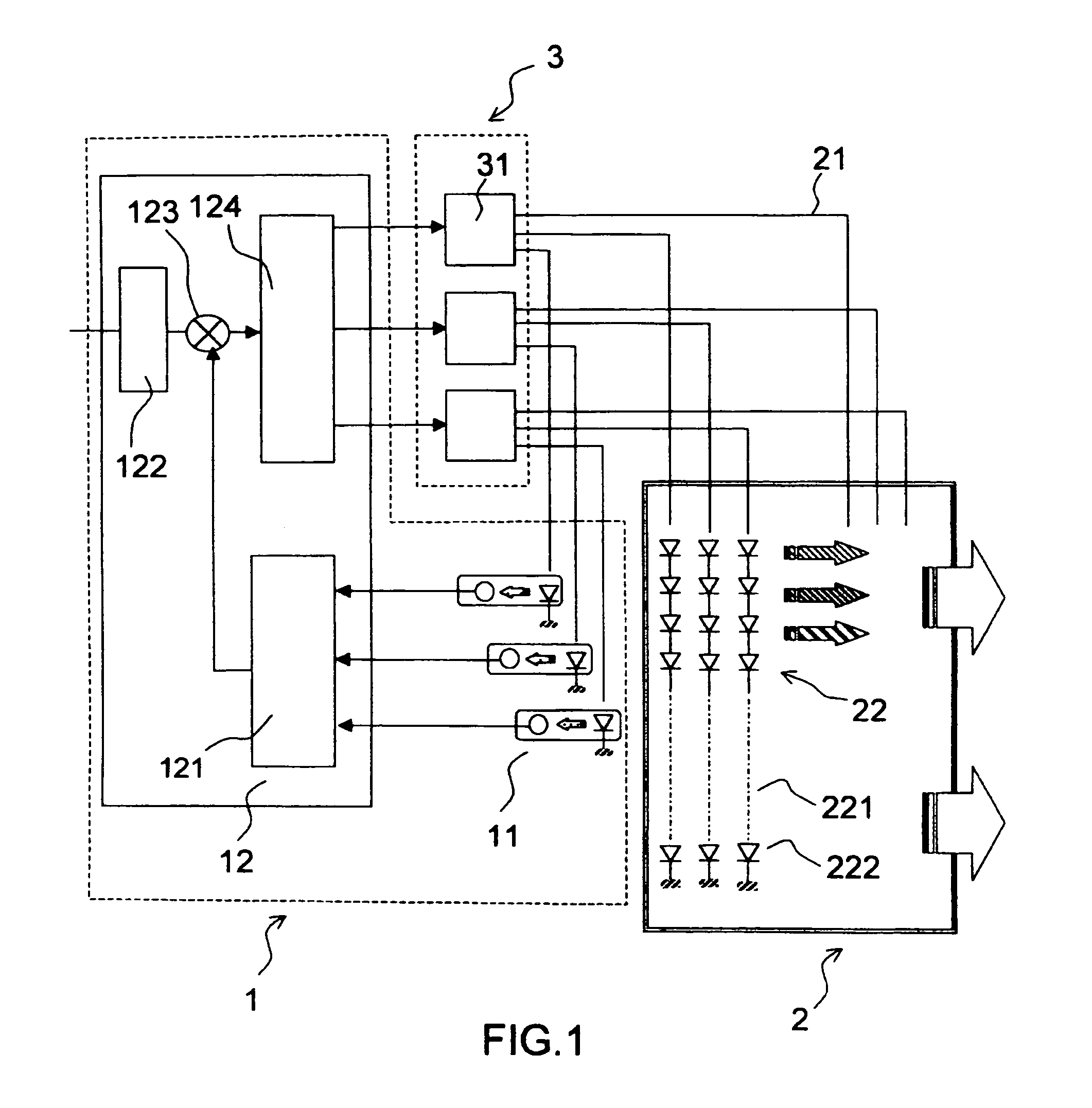
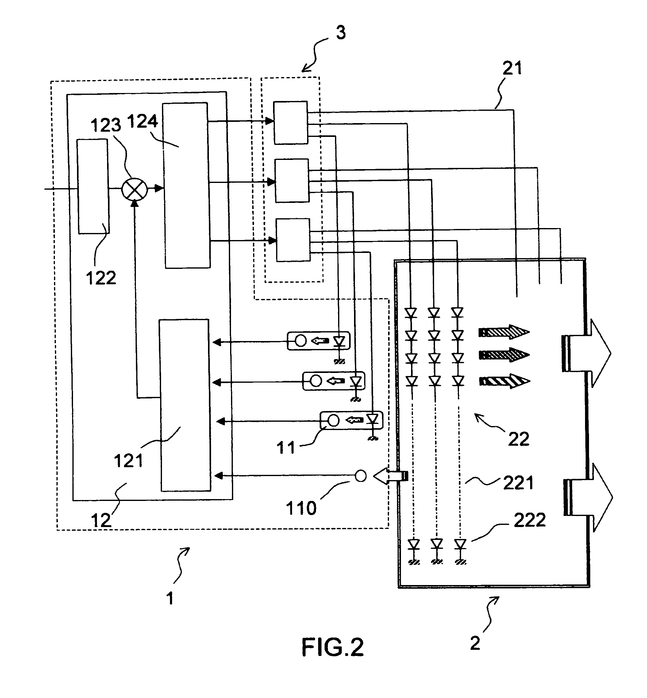
[0065]FIG. 1 shows a general diagram of an electronic assembly that includes the feedback control device according to the invention. The assembly comprises three parts: the light box 2, the feedback control device 1 and a unit comprising the electronic control circuits 3 for the arrays of light-emitting diodes. Each electronic control circuit comprises several control modules 31. Each electronic module 31 controls one type of diode.

[0066]The light box comprises several arrays 22 of diodes as shown in FIG. 1. Each array comprises light-emitting diodes of the same type. Each array 22 is formed from several branches 221 that are connected to an electronic control module 31 via electrical links 21, each branch 221 comprising LEDs 222 of the same type connected in series. Of course, other arrangements are possible (especially matrix arrangements of the LEDs). The light-emitting diodes 222 of the various arrays 22 emit in different spectral bands. Conventionally, to obtain white light, it...


PUM


Abstract

The field of the invention is that of light boxes used for illuminating optical-valve displays, especially matrix liquid-crystal displays (or LCDs). The illumination from light boxes can at the present time be produced by light-emitting diodes that emit in various spectral bands so as to reconstruct white illumination. For a number of applications, in particular aeronautical applications, it is necessary to maintain the photometric and colorimetric characteristics of this illumination independently of the environmental and ageing conditions of the components. The invention provides an electronic feedback control device for maintaining the photometric and colorimetric characteristics of this illumination at given setpoint values without introducing disturbing optoelectronic devices into the light box. Several possible technical solutions are described.

Description

CROSS-REFERENCE TO RELATED APPLICATIONS[0001]The present Application is based on International Application No. PCT / EP2004 / 050388, filed on Mar. 29, 2004, which in turn corresponds to FR 03 / 05125 filed on Apr. 25, 2003, and priority is hereby claimed under 35 USC §119 based on these applications. Each of these applications are hereby incorporated by reference in their entirety into the present application.FIELD OF THE INVENTION[0002]The field of the invention is that of light boxes (LBs) used for illuminating optical-valve displays, especially matrix liquid-crystal displays (or LCDs). It relates more particularly to polychromatic displays having light boxes emitting white light.[0003]The invention relates to the calorimetric and photometric control of the light emitted by said light boxes.[0004]The field of application is more particularly that of displays on board aircraft, but it can be used for any application requiring optical-valve displays having precise calorimetric or photome...

Claims


Application Information

Patent Timeline
Patent Type & Authority Patents(United States)
IPC IPC(8): G09G3/36G09G3/20G09G3/32G09G3/34H01L33/00H05B44/00
CPCG09G3/32G09G3/3413H05B33/0818H05B33/0827H05B33/0869G09G3/2014G09G3/207G09G3/3611G09G2320/0285G09G2320/0626G09G2320/064G09G2320/0666G09G2360/144G09G2380/12H05B45/22H05B45/46H05B45/10
Inventor SCHOU, GUY
Owner THALES SA
Why Eureka
Try Eureka