Laser system

a laser system and laser technology, applied in the field of laser systems, can solve the problems of non-linear optical, inability to anticipate, and inability to accurately predict the coherence of the modes or the information of the offset frequency, and achieve the effect of less maintenance and less maintenan

Active Publication Date: 2010-09-28
MENLO SYST
View PDF14 Cites 23 Cited by
  • Summary
  • Abstract
  • Description
  • Claims
  • Application Information

AI Technical Summary

Benefits of technology

[0021]By means of the Raman shift the laser system of the present invention may successfully shift the frequency comb onto different frequency ranges. Depending on choice and configuration of the Raman medium, the Raman shift may be a Stokes process, during which the modes of the comb are shifted to lower frequencies, or an anti-Stokes process, at which the modes of the comb are shifted to higher frequency.
[0048]It is also conceivable to configure the plurality of fiber sections such that they are different in the cross sectional area of their cores. A smaller core will lead to higher light intensities and, thus, higher nonlinear optical properties.

Problems solved by technology

This could not be expected in particular with respect to the Raman medium, since the Raman shift is an “inelastic”diffusion of light, curing which the coherence of the modes or the information of the offset frequency could easily have been lost.
Moreover, there are other, non-linear optical effects in optical fibers from which it is known that they destroy the coherence, such as modulation instability or Brillouin scattering.

Method used


Image

  • Laser system
  • Laser system
  • Laser system

Examples


Embodiment Construction

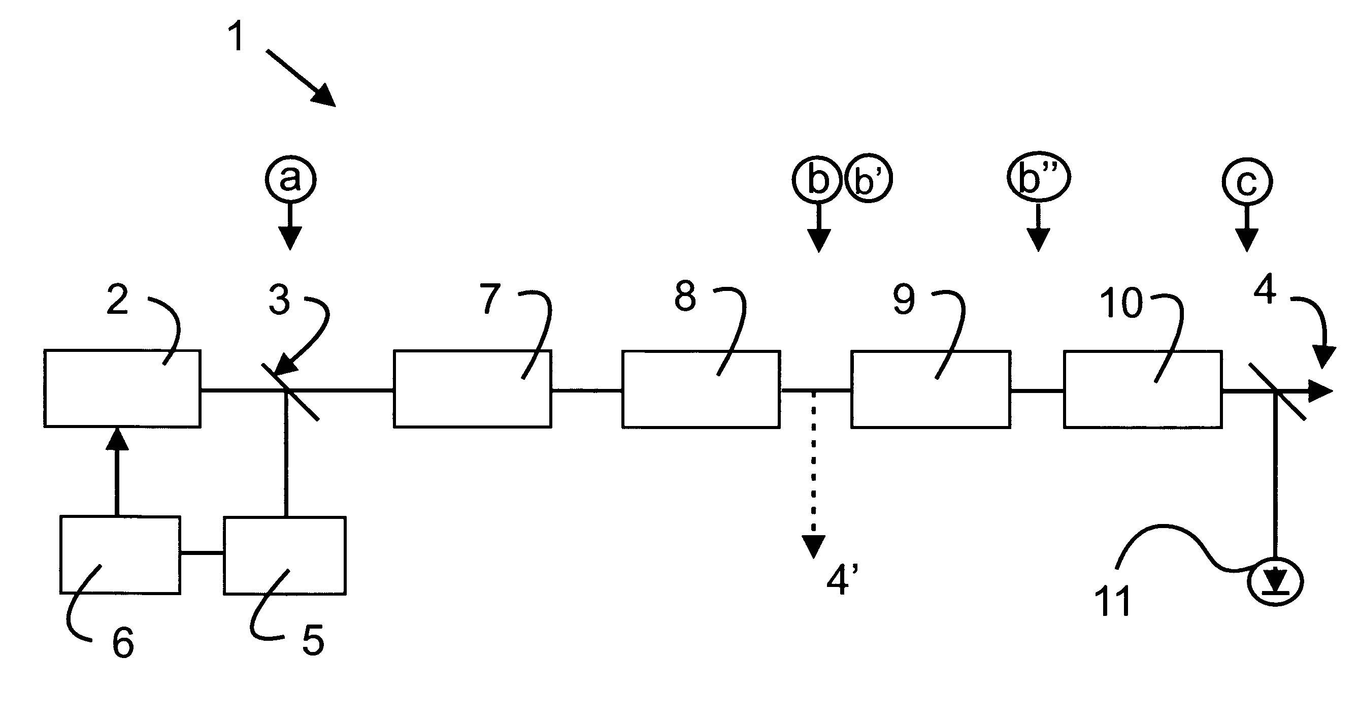
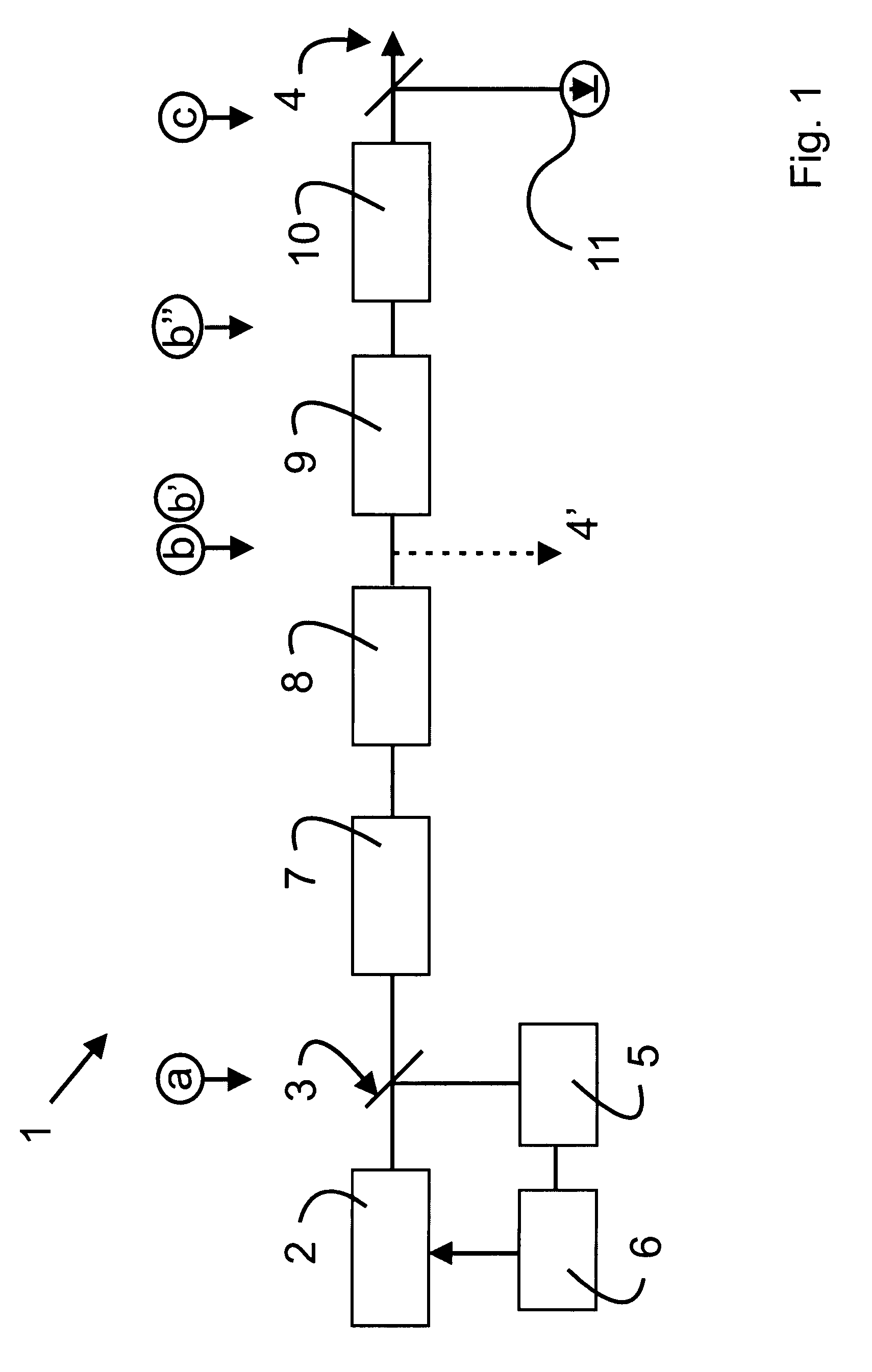
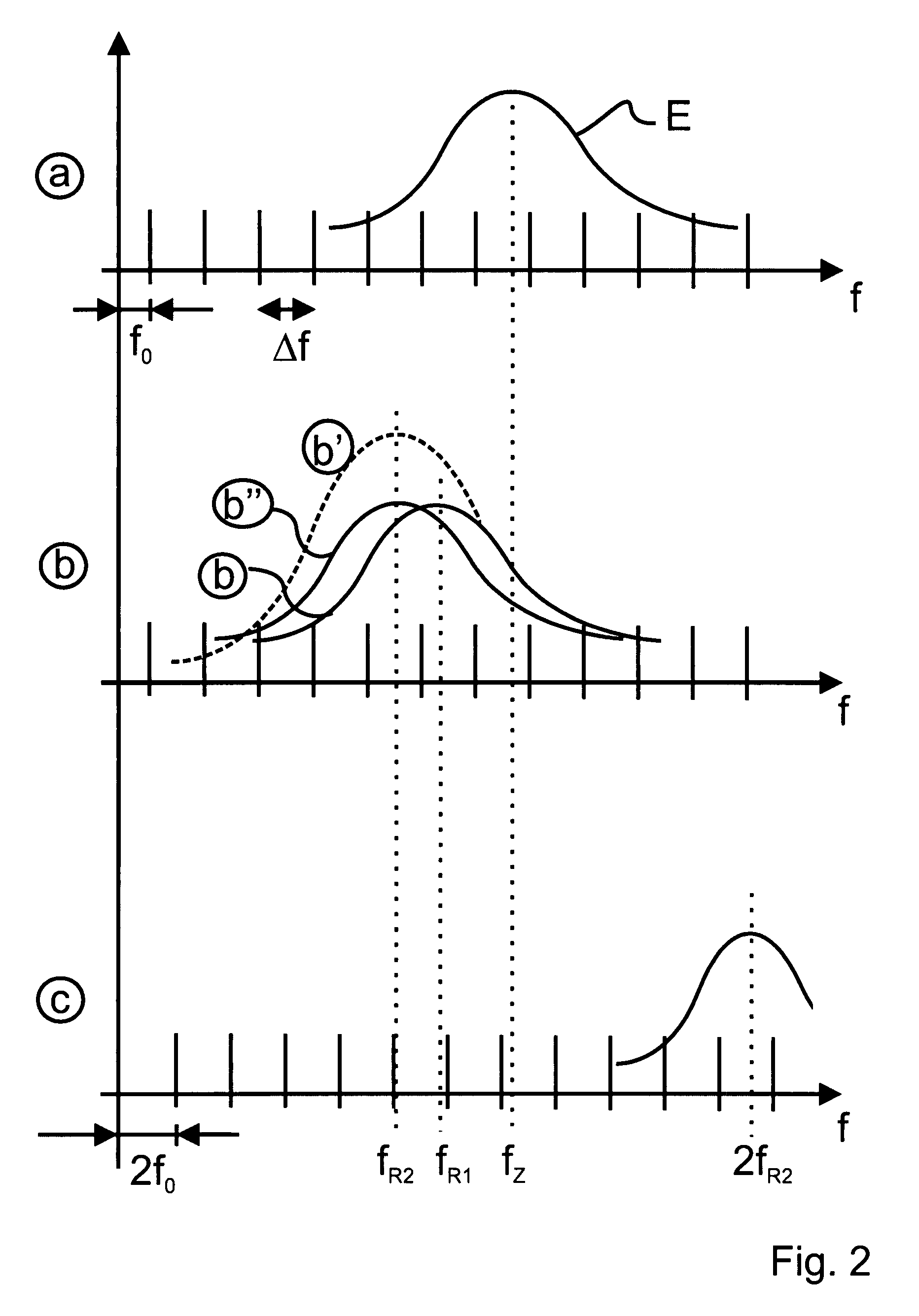
[0054]FIG. 1 is a schematical view of a laser system 1 according to the present invention. Starting point of the laser system is a frequency comb generator 2 for generating a frequency comb of optical frequencies with an offset frequency f0 and a plurality of equidistant nodes fn=f0+n Δf. The frequency comb generator 2 or oscillator may be a diode pumped ultra short pulse fiber laser, for example a femtosecond Er+ fiber laser with a central wavelength of approximately 1550 nm. The repetition rate of the oscillator and, thus, the mode spacing Δf, may be set to a value of, for example, 100 MHz or 200 MHz. The frequency comb coupled out of the frequency comb generator 2 at the position (a) is schematically shown in the first “line” in FIG. 2. It is constituted by the equidistant modes, the amplitudes of which are determined by an envelope E.

[0055]A beam splitter 3 divides the frequency comb into a first portion that is later routed to an exit or output 4 of the laser system 1, and a se...


PUM


Abstract

The invention concerns a laser system with a frequency comb generator for generating a comb of optical frequencies having an offset frequency and a plurality of equidistant modes. The laser system further preferably includes at least one stabilizer for stabilizing the frequency comb onto a certain offset frequency and / or onto a certain mode spacing. The laser system further includes an optical amplifier for amplifying the frequency comb coupled out of the frequency comb generator, the amplification factor of this amplifier being variable; and the amplifier is followed by a Raman medium for generating a Raman shift of the frequency comb.

Description

BACKGROUND OF THE INVENTION[0001]1. Field of the Invention[0002]The present invention is directed to a laser system with a frequency comb generator for generating a frequency comb of optical frequencies with an offset frequency and a plurality of equidistant modes.[0003]2. Prior Art[0004]Such a laser system comprises as an important component a frequency generator as known from DE 199 11 193 A1, the corresponding EP 1 161 782 B1 or DE 100 44 404 C2. In each of these conventional systems, a short pulse or ultra short pulse oscillator is provided as the frequency comb, i.e. a mode locked laser with pulse durations in the range from femtoseconds (fs) to nanoseconds (ns). When performing a Fourier transformation from the time domain into the frequency domain, the sequence of laser pulses corresponds to a “frequency comb” in the frequency domain. This comb is constituted by a plurality of sharp δ-like functions at different discrete frequencies, called modes fn. Adjacent modes have a mut...

Claims


Application Information

Patent Timeline
Patent Type & Authority Patents(United States)
IPC IPC(8): H01S3/30
CPCH01S3/06754H01S3/302G01N21/6458
Inventor ADEL, PETERFISCHER, MARCMEI, MICHAELHOLZWARTH, RONALD
Owner MENLO SYST
Why Eureka
Try Eureka