Method and apparatus for measuring motion of a subject using a series of partial images from an imaging system

a technology of imaging system and partial image, applied in the field of tracking the position of objects, can solve the problems of not always finding good landmarks in diseased tissue, incurring extra costs, and not being able to detect errors in application of directed beams

Active Publication Date: 2010-09-28
CARL ZEISS MEDITEC INC
View PDF24 Cites 66 Cited by
  • Summary
  • Abstract
  • Description
  • Claims
  • Application Information

AI Technical Summary

Benefits of technology

[0017]The embodiment described below applies this invention to a line-scan ophthalmoscope and OCT measurement system, but it will be evident to those skilled in the art that this invention can be applied to line-scan imaging of other moving subjects, and for correcting the placement of other types of optical measurement or optical treatment beams. The tracking information derived from the line-scan imager can be used to correct the line-scan image itself, for example by forming an averaged image in which the tracking information allows one to correctly place lines from several passes of the line scanner into the averaged image. The tracking information can also be used to adjust the scan range of the line-scan imager so that the region of interest remains stationary in the view of the line-scan imager.

Problems solved by technology

These motions cause noticeable errors in application of directed beams such as photocoagulation and optical coherence tomography (OCT).
Faster frame rates are possible, but incur extra cost.
However, good landmarks are not always found in diseased tissue.

Method used


Image

  • Method and apparatus for measuring motion of a subject using a series of partial images from an imaging system
  • Method and apparatus for measuring motion of a subject using a series of partial images from an imaging system
  • Method and apparatus for measuring motion of a subject using a series of partial images from an imaging system

Examples


Embodiment Construction

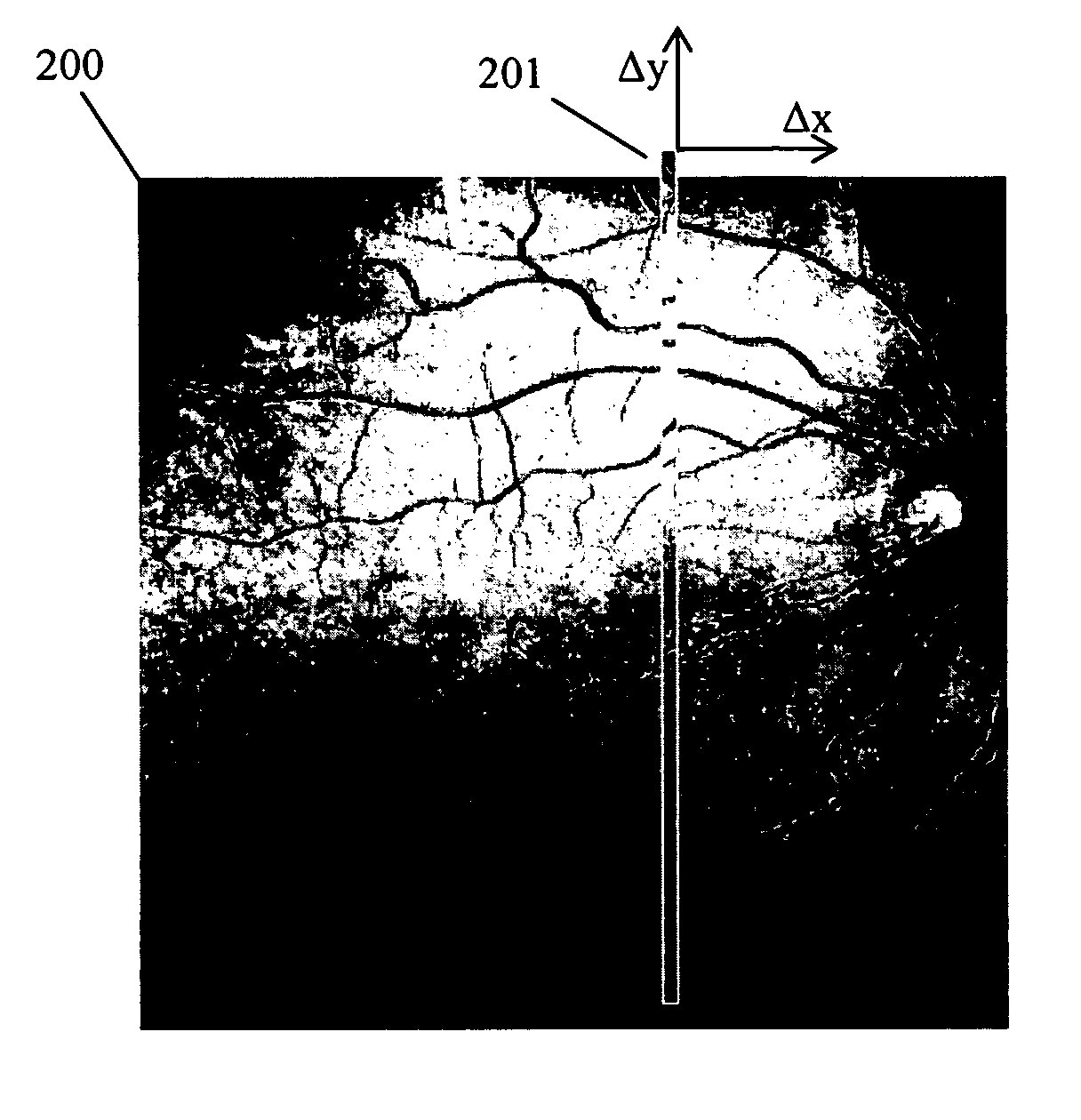
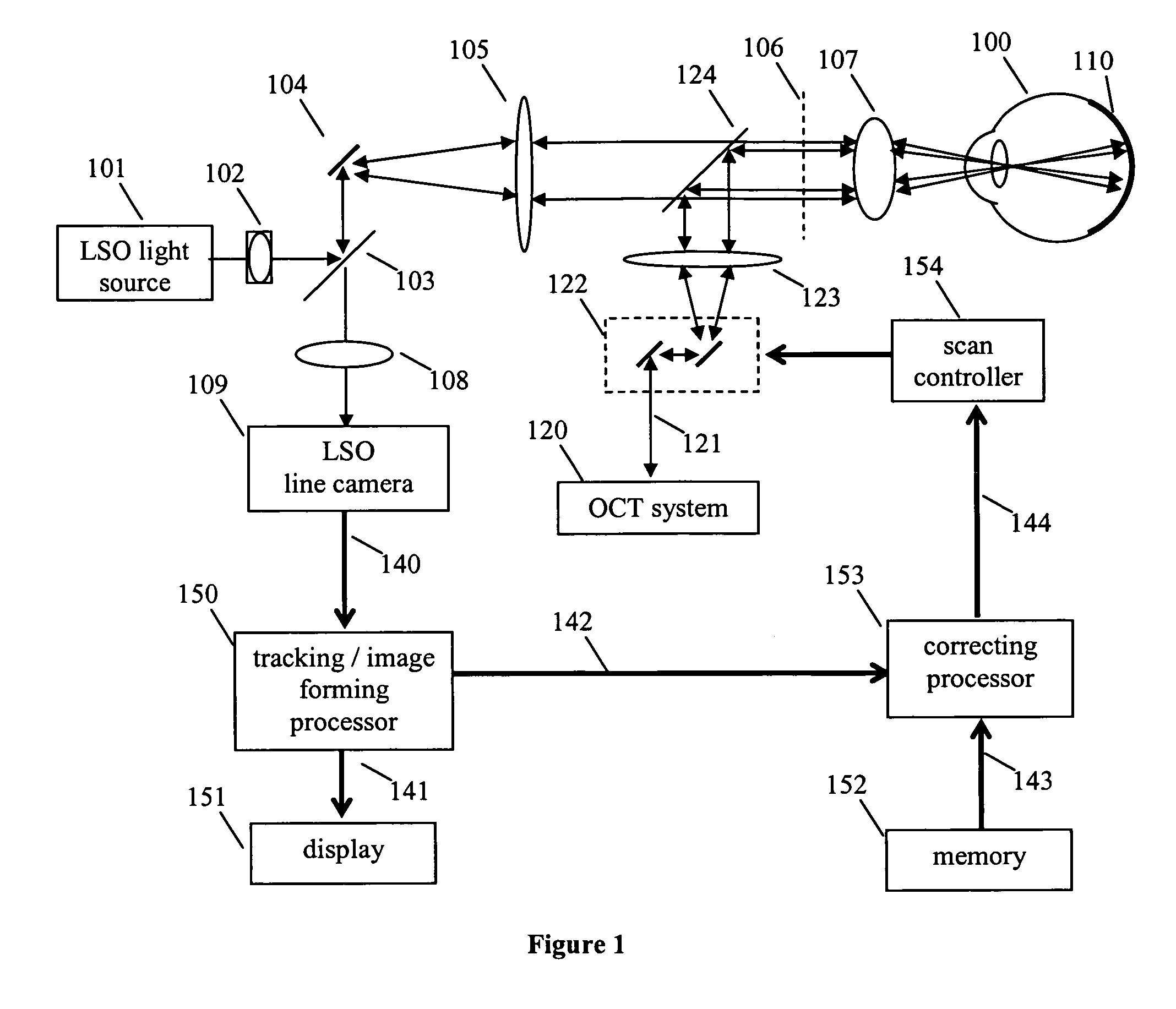
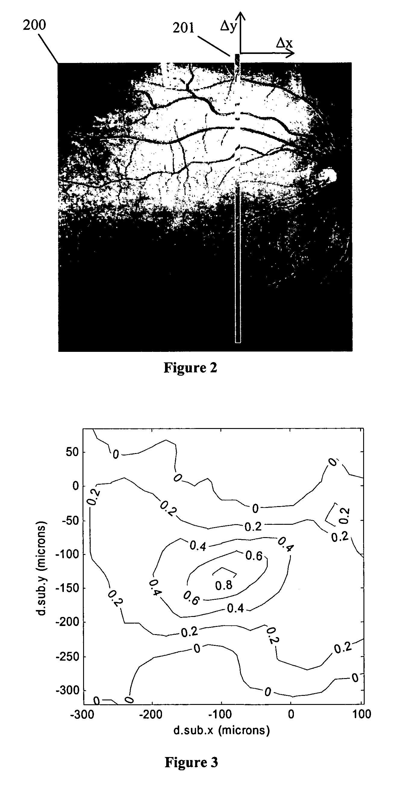
[0023]FIG. 1 is a schematic illustration of an OCT measurement system incorporating eye tracking based on a line-scan ophthalmoscope (LSO). Light from the LSO light source 101 is routed by cylindrical lens 102 and beamsplitter 103 to scanning mirror 104. The cylindrical lens 102 and the scan lens 105 produce a line of illumination at the retinal image plane 106, and the ocular lens 107 and optics of the human eye 100 re-image this line of illumination onto the retina 110. The line of illumination is swept across the retina as the scanning mirror 104 rotates. Reflected light from the retina approximately reverses the path of the LSO illumination light; the reflected light is de-scanned by the LSO scan mirror 104 so that the illuminated portion of the retina is continuously imaged by imaging lens 108 onto the LSO line camera 109. The LSO line camera converts the reflected LSO light into a data stream 140 representing single-line partial images, which are processed to form both eye tra...


PUM


Abstract

A line scan imager is used to determine the motion of a subject. Each line of image data from the line scan imager is compared with a reference image. The location of a matching line in the reference image reveals the displacement of the subject. The current subject displacement can be determined based on each line of image data. The resulting displacement information can be used to correctly place other optical beams on the subject. The method can be applied to tracking the human eye to facilitate measurement, imaging, or treatment with a beam of optical radiation.

Description

PRIORITY[0001]This application claims the benefit of the filing date under 35 U.S.C. §119(e) of Provisional U.S. Patent Application Ser. No. 60 / 668,785, filed on Apr. 6, 2005, which is hereby incorporated by reference in its entirety.TECHNICAL FIELD OF THE INVENTION[0002]The present invention relates to systems for tracking the position of an object. In particular, the invention is a system for determining motion of the eye of a patient, using partial images from a scanning ophthalmoscope. The intended field of application of the invention is to use the tracking information to correct the position of optical treatments or optical measurements made on the patient's eye.BACKGROUND OF THE INVENTION[0003]Directed beams of light are used for both measurement and treatment of patients, and the patient presents a moving subject. In the field of ophthalmology, laser photocoagulation is an example of a treatment method, and optical coherence tomography an example of a measurement method, bot...

Claims


Application Information

Patent Timeline
Patent Type & Authority Patents(United States)
IPC IPC(8): G06K9/68G06K9/00
CPCA61B3/113A61B3/102
Inventor EVERETT, MATTHEW J.FLACHENECKER, CLAUSHACKER, MARTINMEYER, SCOTT A.O'HARA, KEITH E.WILLIAMS, RICK A.
Owner CARL ZEISS MEDITEC INC
Why Eureka
Try Eureka