Pavement joint

a pavement and jointing technology, applied in the direction of paving details, building insulations, building components, etc., can solve the problems of cracking of concrete, buckling and warping of pavement, and all of spalling and crushing of concrete, and achieve the effect of opening or creating a crack

Inactive Publication Date: 2010-10-05
TRIPSTOP TECH
View PDF41 Cites 138 Cited by
  • Summary
  • Abstract
  • Description
  • Claims
  • Application Information

AI Technical Summary

Benefits of technology

[0012]In accordance with the invention, the joint provides a load transfer mechanism that inhibits differential vertical movement of the slabs when at least one of those slabs is affected by an out-of-plane action such as by tree root invasion or by soil movement. By reducing the differential vertical movement of the contiguous slabs, potential tripping hazards to pedestrians are reduced. Along with this, as pavements are less likely to require repair or replacement, there is a future cost saving to users and a reduction in waste of resources.
[0048]In yet a further aspect, the present invention provides a method of inhibiting differential out-of-plane movement of contiguous slabs in a pavement under an out-of-plane action applied to at least one of the slabs by incorporating pavement joints between the contiguous slabs, the joints being elongate and each extending along a joint axis and being capable of transferring shear between the slabs and accommodating angular displacement of the slabs relative to the joint axis in at least one direction.

Problems solved by technology

The coefficient of thermal expansion of concrete is commonly in the order of 12 micro strain per degree Celsius or approximately 0.4 mm in a slab 1500 mm long subjected to a temperature change of 20 deg. C. If contraction is restrained, it may lead to cracking of the concrete.
If expansion is restrained it may lead to any or all of spalling and crushing of the concrete and buckling and warping of the pavement.
This encourages cracking to occur at such grooves rather than in a random fashion, which would be unsightly, and helps to create many narrow cracks rather than few large cracks, which would be detrimental.
In the case of un-reinforced concrete footpaths for example, which have relatively closely spaced contraction joints, the uplifting action of a tree root will typically lead to the opening or creation of a crack emanating from the top surface of the footpath at a contraction joint adjacent to the point of uplifting.
However, the cracking of this construction joint only reduces the flexural strength of a slab significantly in one direction and the aforementioned lifting may lead to the sudden, uncontrolled fracture of the footpath at distances from the point of lifting corresponding to the flexural strength of the concrete.
Further, if a crack is relatively wide, a lifted slab may not engage its neighbour with the result that a vertical discontinuity or step will be created in the pavement.
In the case of footpaths this often leads to steps of sufficient height to impair the passage of pedestrian vehicles and to cause pedestrians to trip or fall.
Such joints have no ability to transfer load or to limit differential displacement within a pavement.

Method used


Image

  • Pavement joint
  • Pavement joint
  • Pavement joint

Examples


example 1 (

Rigid)

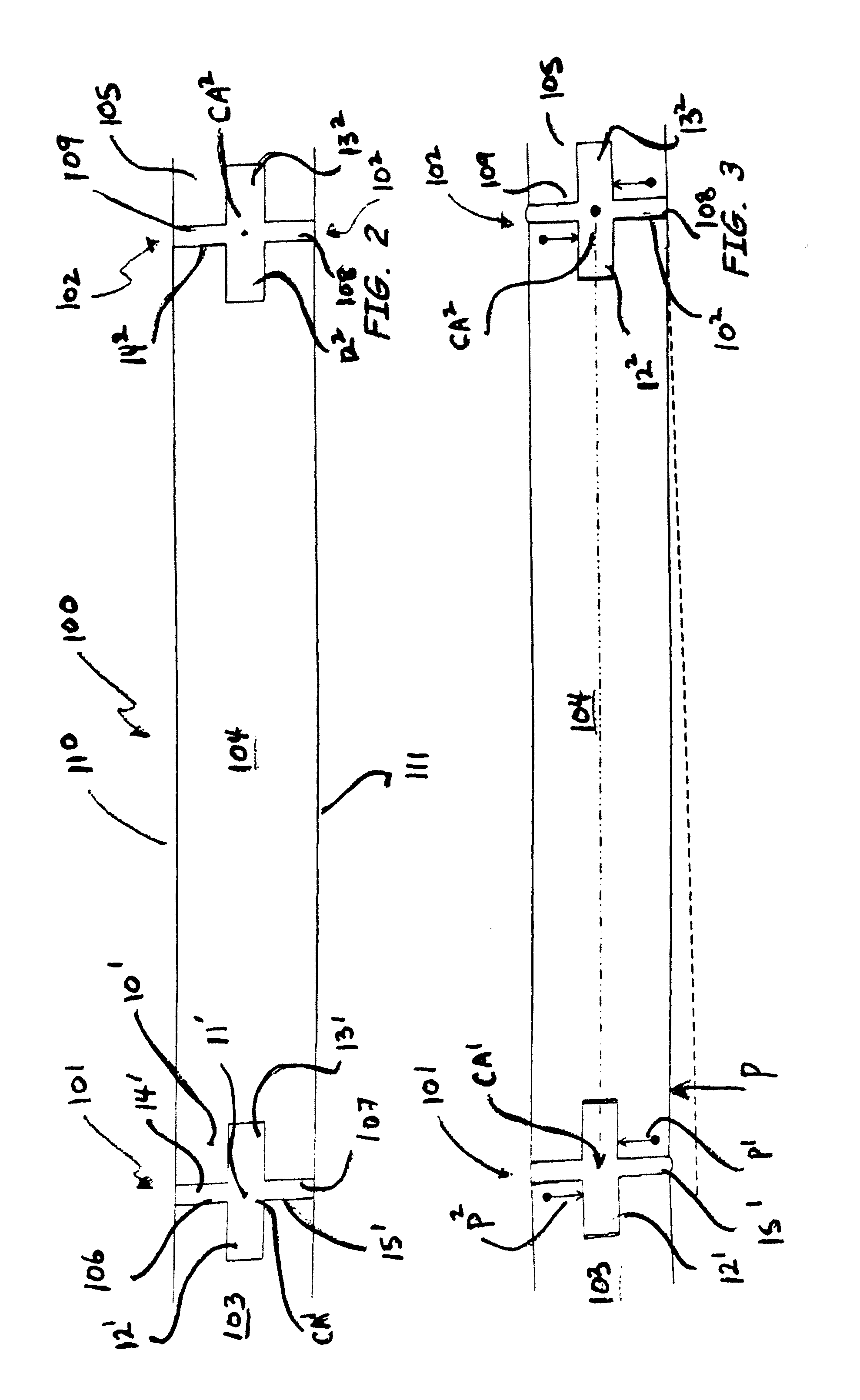
[0124]A full scale prototype concrete footpath was constructed at RMIT University, Melbourne, Australia. The prototype was 5 m long, 1.5 m wide and 75 mm thick. It was cast on a steel frame, designed in such a way that the formwork could be removed from underneath and so that the prototype could be jacked up from virtually any point— to simulate various scenarios of tree root invasion and soil expansion / movement. Four joint members made from rigid PVC were installed in the footpath. They were 1.5 m apart from each other thus dividing the footpath into three 1.5 m long slabs, plus two 250 mm long end slabs. The ends of the footpath were restrained by steel angles. The cross-sectional shape of the joint member was substantially as the same as shown in FIG. 4.

[0125]The prototype was cast using concrete with a nominal strength of 40 MPa. Prior to casting, the slump of the concrete was measured at 90 mm. All tests were conducted after the cylinder strength of concrete of slabs exce...

example 2 (

Flexible)

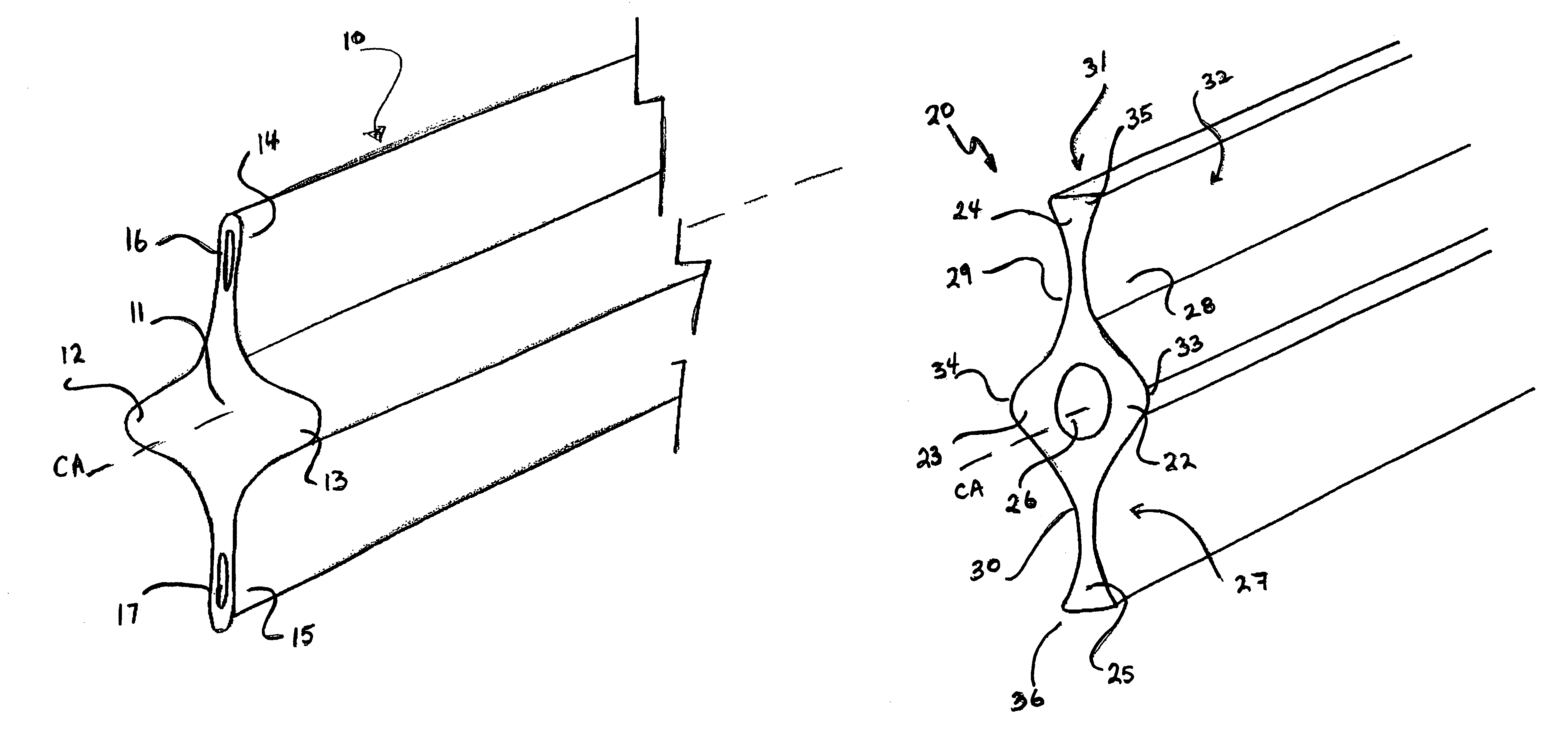
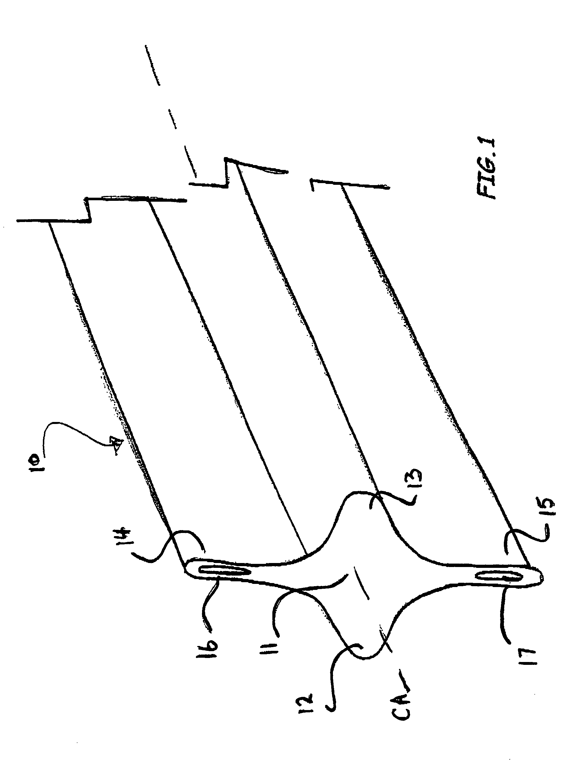
[0132]A full scale prototype concrete footpath similar to that described in Example 1 was constructed at RMIT University, Melbourne, Australia. Four joint members made from EPDM (Ethylene Propylene Diene Monomer) rubber were installed at the same spacings as Example 1. Their shape was substantially as shown in FIG. 1. All tests were conducted after the concrete had been cured for more than 28 days. The 28 day mean compressive strength of the concrete was 21.2 MPa.

[0133]A series of tests similar to those described in Example 1 was carried out. In the first, the concrete slabs were jacked up from the bottom of Slab 2 along line AB (refer to FIG. 18). No additional load was applied to any of the slabs. The maximum average differential displacement on joint 3 was 3 mm.

[0134]At a maximum distributed load on slab 3 of 490 kg, the maximum average differential displacement at joint 3 was 3.5 mm. In the worst case scenario, with slab 1 jacked up at point C and a point load of 200 kg...


PUM

PropertyMeasurementUnit
relative vertical displacementaaaaaaaaaa
thickaaaaaaaaaa
thickaaaaaaaaaa

Abstract

A pavement joint 101, 102 disposed between two contiguous pavement slabs 103, 104 and 105 incorporating a shear key (12, 13, 22 and 23) and at least one hinge (37, 38, 39 and 40). The shear key and the at least one hinge are operative when at least one of the slabs is subjected to out-of-plane action P with the shear key transferring shear between the slabs, and the at least one hinge accommodating angular displacement of the slabs relative to the joint axis in at least one direction. In one form, a joint member 10, 20, 40, 50 and 60 is disposed between the slabs to provide the shear key and hinge. A joint member and pavement slab for use in the joint is also described.

Description

RELATED APPLICATION[0001]The present application is a continuation in part application of U.S. application Ser. No. 10 / 381,289 filed 22 Apr. 2003 now abandoned, which is related to and claims the benefit under 35 U.S.C. §119 and 35 U.S.C. §365 of International Application No. PCT / AU2001 / 01233, filed Sep. 28, 2001, the contents of which are herein incorporated by cross reference.FIELD OF THE INVENTION[0002]The present invention relates generally to the construction of pavements and to jointing systems for use in such pavements. The invention has particular application to pavements that are susceptible to differential movement by out-of-plane action such as for example by tree root invasion, or soil movement, and which usually bear traffic that can accept some irregularity in the pavement surface and the invention is herein described in that context.BACKGROUND OF THE INVENTION[0003]Pavements are used to facilitate the passage of wheeled or pedestrian traffic along or over roads, footp...

Claims


Application Information

Patent Timeline
Patent Type & Authority Patents(United States)
IPC IPC(8): E01C11/04E01C11/02E01C11/10
CPCE01C11/106
Inventor MCLEAN, PETER CHARLESMCCLELLAND, CHRISTOPHER RAYMOND
Owner TRIPSTOP TECH
Why Eureka
Try Eureka