Imaging sensor system with staggered arrangement of imaging detector subelements, and method for locating a position of a feature in a scene

a sensor system and image technology, applied in the field of lightimaging sensor systems, can solve the problems of loss of sensitivity, natural locational uncertainty of image within the detector subelement, locational uncertainty, etc., and achieve the effect of improving the positional accuracy of image location determination, improving the locating of the position of the feature in the scene, and increasing the accuracy of determined location

Active Publication Date: 2010-10-05
RAYTHEON CO
View PDF14 Cites 7 Cited by
  • Summary
  • Abstract
  • Description
  • Claims
  • Application Information

AI Technical Summary

Benefits of technology

[0007]The present invention provides a structure of the detector array that results in increased positional accuracy of the determination of the image location, and a method for signal analysis that improves the locating of the position of the feature in the scene. The accuracy of the determined location is increased by as much as a factor of two. The sensitivity of the detector array is not compromised and may in fact be improved. The present approach is compatible with other known sensor technologies such as the use of filters placed between the scene and the detector array, so that a range of spectral bands may be viewed. No changes to the optics system are required to achieve the improved accuracy determination. There is little cost increase associated with the present approach.
[0011]The one-dimensional detector array achieves two-dimensional imaging by scanning the one-dimensional detector array in a direction perpendicular to the lengthwise direction of the one-dimensional detector array. The scanning may be accomplished using a scanning mechanism that scans the one-dimensional detector array in a direction perpendicular to the length of the detector subelements, or by mounting the optics system and the one-dimensional detector array on a moving platform whose motion produces the scanning effect.
[0012]By overlapping the detector subelements in the optimum manner, the accuracy of the determination of the position of the image of the feature in the scene may be improved significantly, by as much as a factor of 2. This allows the feature to be tracked more precisely and analyzed more precisely to ascertain its nature.
[0013]The present concepts may be further applied to improve the sensitivity of two-dimensional staring detector arrays. An imaging sensor system comprises an optics system that images a point feature of a scene at an image plane as a blur-circle image having a blur-circle diameter, and a detector array at the image plane. The detector array is a two-dimensional detector array comprising a plurality of detector subelements, and the detector subelements are sized and staggered such that an area of the blur-circle image may not simultaneously be split equally among four detector subelements. In one embodiment, the detector subelements are square in plan view. In another embodiment, the detector subelements are rectangular in plan view. Optimally, each detector subelement is rectangular in plan view with a length of m blur diameters, a lengthwise overlap of 1 blur diameter relative to a laterally adjacent detector subelement, and a staggered pattern of detector subelements that repeats every m laterally adjacent rows, where m is a positive integer.

Problems solved by technology

However, in both the one-dimensional and two-dimensional detector arrays, there is a natural locational uncertainty of the image within the detector subelement.
If the detector subelements are made smaller to reduce this uncertainly, “edge effects” between adjacent detector subelements introduce a locational uncertainty, as the image of the feature may not fall entirely within a single detector subelement, as well as a loss of sensitivity because the signal energy of the feature is split between two or more detector subelements.
The accuracy of the location determination is thus limited by the geometry and absolute size of the detector subelements.

Method used


Image

  • Imaging sensor system with staggered arrangement of imaging detector subelements, and method for locating a position of a feature in a scene
  • Imaging sensor system with staggered arrangement of imaging detector subelements, and method for locating a position of a feature in a scene
  • Imaging sensor system with staggered arrangement of imaging detector subelements, and method for locating a position of a feature in a scene

Examples


Embodiment Construction

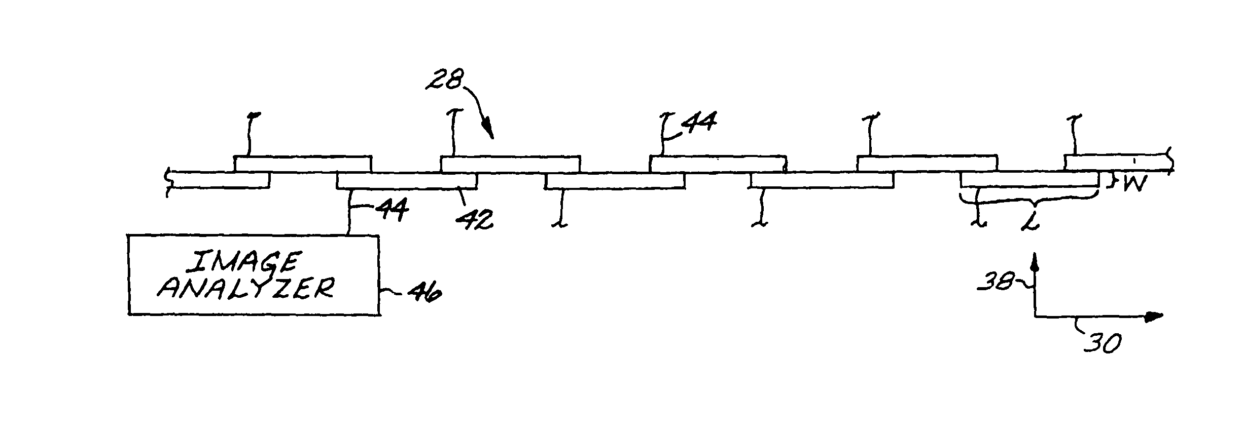
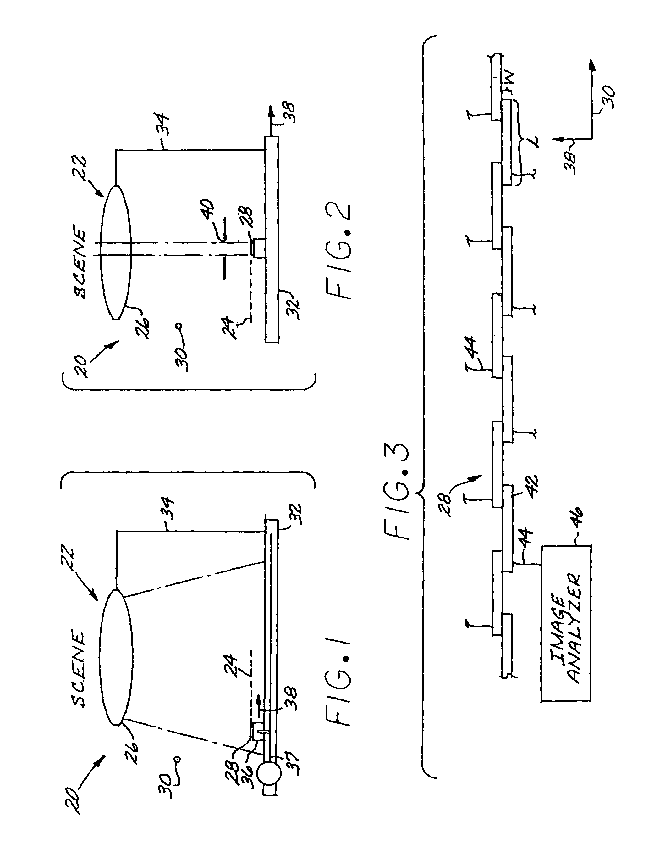
[0034]FIGS. 1-2 each depict an imaging sensor system 20 including an optics system 22 that images a feature of a scene at an image plane 24. The optics system 22 may be of any type, and may include lenses, mirrors, and or other optical components in any operable combination to address a specific imaging requirement. In the figures, the optics system 22 is schematically depicted as a single lens 26, but it is typically more complex than that. The scene feature is projected on the image plane 24 with some blurring, due to aberration and diffraction effects of the optical system. The blur of high-quality optical systems tends to be dominated by diffraction effects of the optical system, and the blur of low-cost systems by aberrations. In all cases, each point in the scene is imaged as a blur spot. The diameter of this spot is referred to as a “blur diameter”, and is a characteristic of the optics system 22. Blur most often is discussed as a circular disk, even though it may in fact hav...


PUM


Abstract

An imaging sensor system includes an optics system that images a point feature of a scene at an image plane with a blur-circle image having a blur diameter, and a detector array at the image plane. Special array patterns and signal detector logic are used to improve the accuracy of the determination of the object location. In one form, the detector array is a one-dimensional detector array comprising a plurality of detector subelements each having a width of from about ½ to about 5 blur diameters, and a length of n blur diameters. Each detector subelement overlaps each of two adjacent detector subelements along their lengths. An overlap of each of the two adjacent detector subelements is m blur diameters, and a center-to-center spacing of each of the two adjacent detector subelements is nO blur diameters. The value of n is equal to about 3m, and the value of m is equal to about nO / 2. In another form, the detector is a two-dimensional detector array of detector subelements. The detector subelements are sized and staggered such that an area of the blur-circle image may not simultaneously be split equally among four detector subelements.

Description

[0001]This invention relates to an imaging sensor system that employs a segmented detector array and, more particularly, to an approach for improving the accuracy of the determination of the image location on the segmented detector array by overlapping the detector subelements.BACKGROUND OF THE INVENTION[0002]In a typical light-imaging sensor system, a feature in a scene is imaged onto an image surface by optical elements such as lenses and mirrors. A detector segmented array formed of a number of detector subelements is located at the image surface, so that the feature is imaged onto the detector array. The output signals of the detector subelements are amplified and supplied to an image-processing computer, which determines the location and nature of the image of the feature.[0003]The detector array may be a one-dimensional or linear array of detector subelements that is optionally scanned over the scene to produce a two-dimensional image. The detector array may instead be a two-d...

Claims


Application Information

Patent Timeline
Patent Type & Authority Patents(United States)
IPC IPC(8): H01L27/00
CPCH01L27/14601H04N5/3694H04N25/7013
Inventor O'NEILL, MARY MORABITOPIERCE, GREGORY K.WELLMAN, WILLIAM H.
Owner RAYTHEON CO
Why Eureka
Try Eureka