Liquid crystal device and electronic apparatus
a liquid crystal device and electronic equipment technology, applied in the field of display devices, can solve the problems of inability to ensure a good sensitivity in the detection of pointing objects, and inability to achieve a good sensitivity in the detection of objects, so as to reduce unwanted irradiation of light, reduce the effect of undesirable irradiation
- Summary
- Abstract
- Description
- Claims
- Application Information
AI Technical Summary
Benefits of technology
Problems solved by technology
Method used
Image
Examples
first embodiment
1: First Embodiment
1-1: General Configuration of Liquid Crystal Device
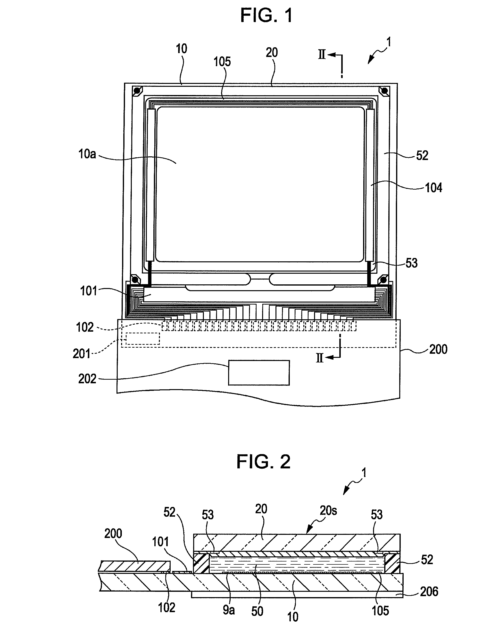
[0042]As illustrated in FIGS. 1 and 2, in the configuration of a liquid crystal device 1 according to the present embodiment of the invention, a TFT array substrate 10 and a counter substrate 20 are provided in such a manner that they face each other, that is, at positions opposite each other. The TFT array substrate 10 is a non-limiting example of a “first substrate” according to the invention, whereas the counter substrate 20 is a non-limiting example of a “second substrate” according to the invention. A liquid crystal layer 50 is sealed between the TFT array substrate 10 and the counter substrate 20. The TFT array substrate 10 and the counter substrate 20 are adhered to (e.g., bonded to) each other with the use of a sealant material 52 that is provided at a sealing region around an image display region 10a. The image display region 10a is a display area in which a plurality of pixel units (i.e., a plurality of ...
second embodiment
2: Second Embodiment
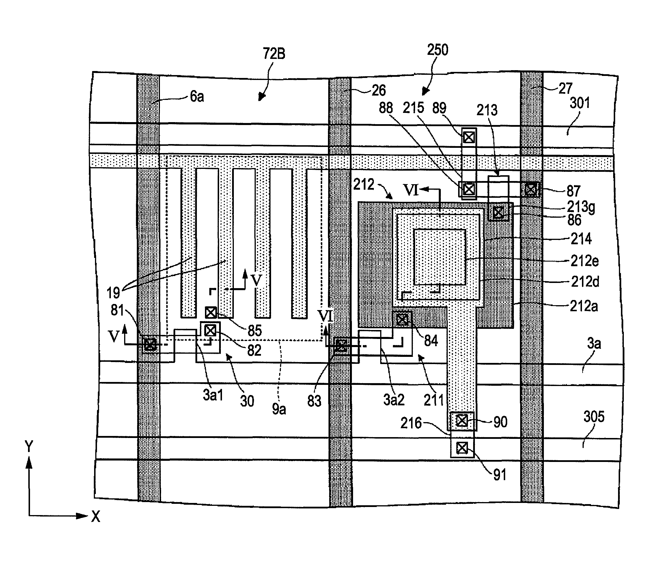
[0079]Next, with reference to FIGS. 7-9, a liquid crystal device according to a second embodiment of the invention is explained below. FIG. 7 is a plan view that schematically illustrates an example of the configuration of the sub pixel unit 72B-1 and the optical sensor unit 250 of a liquid crystal device according to a second embodiment of the invention. FIG. 8 is a sectional view taken along the line VIII-VIII of FIG. 7. FIG. 9 is a sectional view taken along the line IX-IX of FIG. 7. In the following description, the same reference numerals are assigned to the same components as those of the liquid crystal device 1 according to the first embodiment of the invention described above, and detailed explanation thereof is omitted.
[0080]As illustrated in FIG. 7, the sub pixel unit 72B-1 has the pixel electrode 9b. The pixel electrode 9b of the sub pixel unit 72B-1 is electrically connected to the TFT 30 thereof via two contact holes, that is, the contact hole 81 and...
third embodiment
3: Third Embodiment
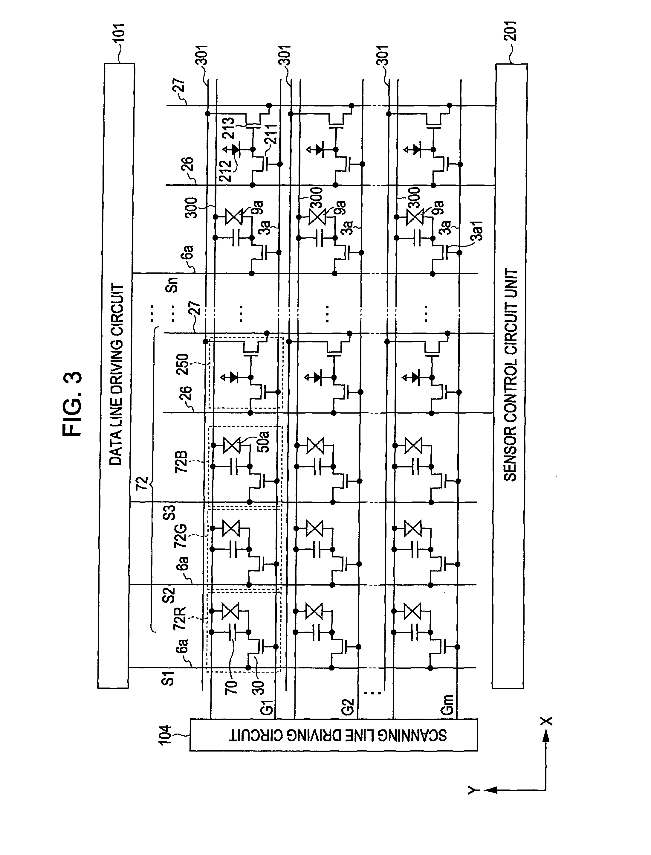
[0084]Next, with reference to FIGS. 10-12, a liquid crystal device according to a third embodiment of the invention is explained below. FIG. 10 is an equivalent circuit diagram that illustrates an example of constituent elements and wirings in a plurality of pixels that are arranged in a matrix pattern so as to constitute the image display region 10a of a liquid crystal device according to the present embodiment of the invention. FIG. 11 is a plan view that schematically illustrates an example of the configuration of the sub pixel unit 72B-2 and the optical sensor unit 250 of a liquid crystal device according to a third embodiment of the invention. FIG. 12 is a sectional view taken along the line XII-XII of FIG. 11.
[0085]The liquid crystal device according to the third embodiment of the invention illustrated in FIG. 10 differs from the above-described liquid crystal device according to the first or second embodiment of the invention in that one electrode of the PI...
PUM
| Property | Measurement | Unit |
|---|---|---|
| transparent | aaaaa | aaaaa |
| electric | aaaaa | aaaaa |
| electric potential | aaaaa | aaaaa |
Abstract
Description
Claims
Application Information
 - R&D
- Intellectual Property
- Life Sciences
- Materials
- Tech Scout
- Unparalleled Data Quality
- Higher Quality Content
- 60% Fewer Hallucinations
Browse by: Latest US Patents, China's latest patents, Technical Efficacy Thesaurus, Application Domain, Technology Topic, Popular Technical Reports.
© 2025 PatSnap. All rights reserved.Legal|Privacy policy|Modern Slavery Act Transparency Statement|Sitemap|About US| Contact US: help@patsnap.com


