
Control apparatus and method and control unit

a control apparatus and control technology, applied in the direction of adaptive control, electric control, instruments, etc., can solve problems such as degraded control accuracy

Inactive Publication Date: 2010-10-12
HONDA MOTOR CO LTD
View PDF8 Cites 24 Cited by
  • Summary
  • Abstract
  • Description
  • Claims
  • Application Information

AI Technical Summary

Benefits of technology

This approach improves control accuracy and maintains excellent exhaust emission reduction rates by quickly correcting fluctuations in the control input, even under sudden changes in engine operating conditions.

Problems solved by technology

Since the control input is thus calculated, when the error of the control input with respect to the estimated value of the control input is suddenly increased due to a sudden change in the dynamic characteristics of the controlled object, it takes time to compensate for the error using the first input value since the first input value is calculated with the feedback control algorithm, resulting in degraded control accuracy.

Method used


Image

  • Control apparatus and method and control unit
  • Control apparatus and method and control unit
  • Control apparatus and method and control unit

Examples


first embodiment

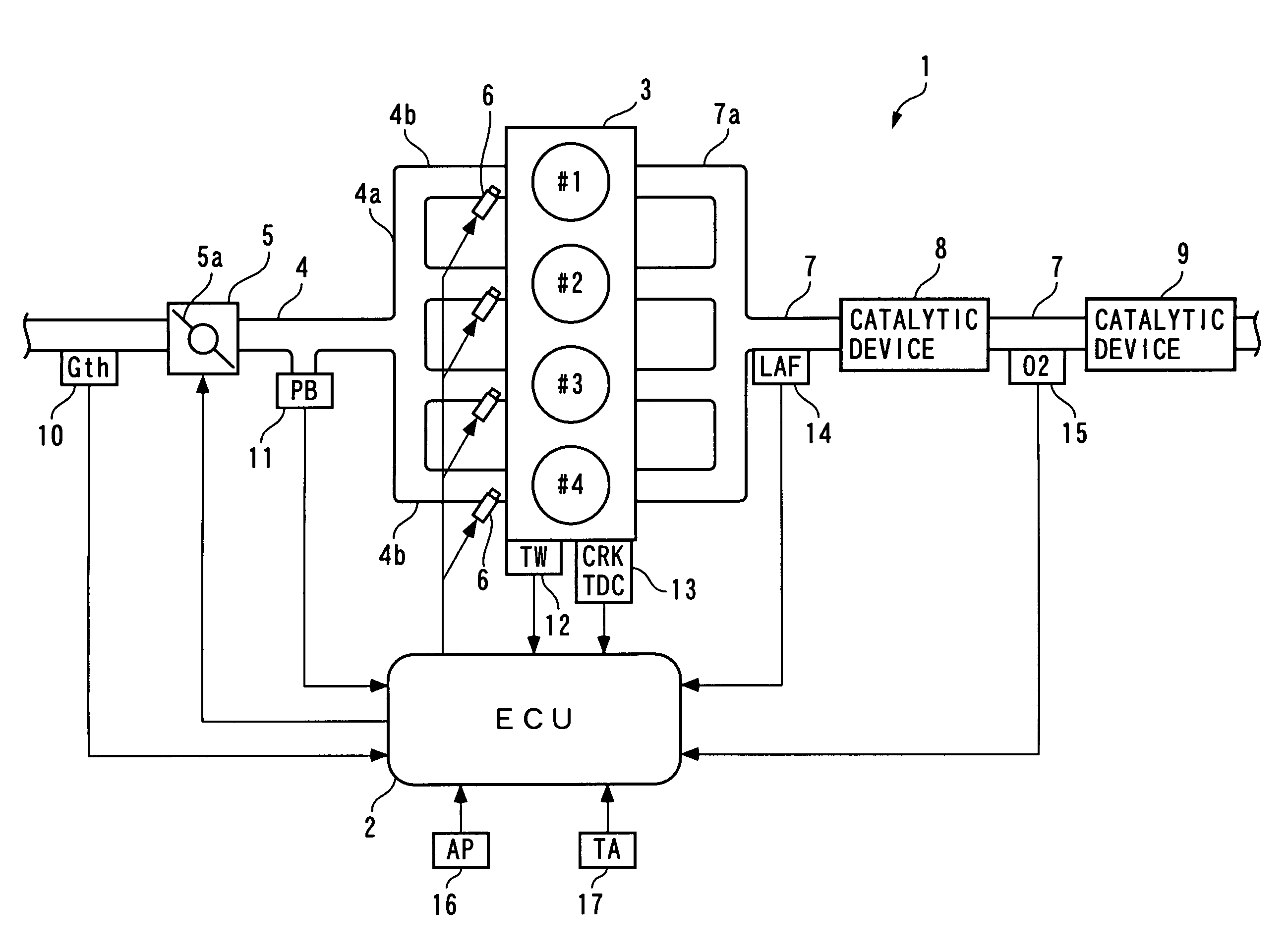
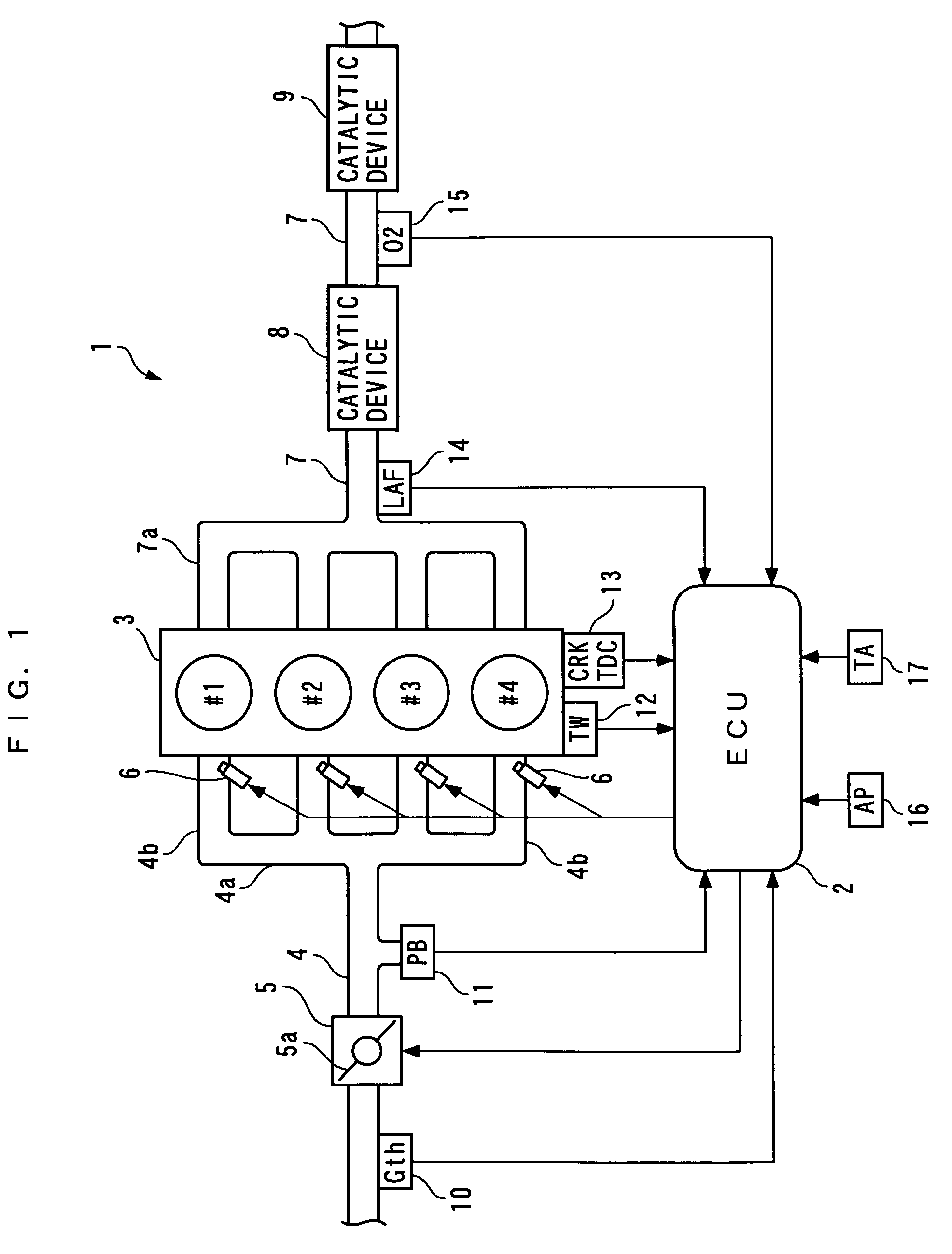
[0090]Hereafter, a control apparatus according to the present invention will be described with reference to the drawings. The control apparatus according to the present embodiment is for controlling the air-fuel ratio of a mixture to be supplied to an internal combustion engine. FIG. 1 is a schematic diagram of the control apparatus 1, and the internal combustion engine (hereinafter referred to as “the engine”) 3 to which is applied the control apparatus. Referring to FIG. 1, the control apparatus 1 includes an ECU 2. As described hereinafter, the ECU 2 controls the air-fuel ratio of a mixture to be supplied to cylinders of the engine 3, depending on operating conditions of the engine 3.

[0091]The engine 3 is an inline four-cylinder gasoline engine installed on a vehicle (not shown) with a stepped automatic transmission (not shown) mounted thereon, and includes first to fourth cylinders #1 to #4. An air flow sensor 10, a throttle valve mechanism 5, and an intake pressure sensor 11 ar...

second embodiment

[0302]As described above, according to the control apparatus 1A of the second embodiment, the torque feedback value TRQFB is calculated such that the drive wheel speed Ws_act converges to the target wheel speed Ws_cmd, and the modulated value TRQFB_DSM is calculated by modulating the torque feedback value TRQFB with the algorithm to which is applied the ΔΣ modulation algorithm. This causes the modulated value TRQFB_DSM to be calculated as a value exhibiting an inverting behavior at a high frequency (e.g. a frequency of not lower than 5 Hz), since when Ws_act≈Ws_cmd holds, TRQFB≈0 holds.

[0303]Further, the demanded torque TRQDRV is calculated according to the engine speed NE and the accelerator pedal opening AP, a smaller one of the adaptive limit torque TRQFF_LMT and the demanded torque TRQDRV is selected as the feedforward torque TRQFF, and the limit torque TRQTC is calculated by adding the modulated value TRQFB_DSM to the feedforward torque TRQFF. Further, a smaller one of the limi...


PUM


Abstract

A control apparatus which can improve the accuracy of control of a controlled variable by a control input exhibiting a periodic fluctuating behavior. The control apparatus calculates an air-fuel ratio correction value DKCMD such that the output from an oxygen concentration sensor converges to a target output, and calculate a modulated value DKCMD_DSM by modulating DKCMD with an algorithm to which is applied a ΔΣ modulation algorithm. Further, the control apparatus calculates a reference air-fuel ratio KCMDBS according to an exhaust gas volume, calculates a model modification coefficient KTRQFF using a modification coefficient calculated such that DKCMD become equal to 0, calculates an adaptive reference air-fuel ratio KCMDADP by the equation of KCMDADP=KCMDBS×KTRQFF, and calculates a target air-fuel ratio KCMD by the equation of KCMD=KCMADP+DKCMD_DSM.

Description

BACKGROUND OF THE INVENTION[0001]1. Field of the Invention[0002]The present invention relates to a control apparatus and method and a control unit which modulate a value calculated by a feedback control method such that a controlled variable is caused to converge to a target controlled variable, with a predetermined modulation algorithm, to thereby calculate a control input to a controlled object using the modulated value.[0003]2. Description of the Related Art[0004]As a control apparatus for controlling the air-fuel ratio of a mixture supplied to an internal combustion engine, the present assignee has already proposed a control apparatus disclosed in Japanese Laid-Open Patent Publication (Kokai) No. 2000-234550. This control apparatus is comprised of a LAF sensor, an oxygen concentration sensor, a state predictor, an onboard identifier, a sliding mode controller, and a target air-fuel ratio-calculating section. The LAF sensor and the oxygen concentration sensor are each for detecti...

Claims


Application Information

Patent Timeline
Patent Type & Authority Patents(United States)
IPC IPC(8): F02D41/00G06F7/70
CPCF02D41/1403F02D41/1441F02D41/1445F02D41/2458G05B13/04G05B21/00F02D2041/1423
Inventor YASUI, YUJIKAWASUMI, IKUE
Owner HONDA MOTOR CO LTD
Learn More