Plastic gear

a technology of gear and plastics, applied in the direction of gearing elements, belts/chains/gearrings, hoisting equipments, etc., can solve the problems of low impact resistance, high cost, vibration and noise, etc., and achieve low noise, high fatigue strength, and low vibration

Active Publication Date: 2010-10-19
SUZUKI MOTOR CORP
View PDF31 Cites 32 Cited by
  • Summary
  • Abstract
  • Description
  • Claims
  • Application Information

AI Technical Summary

Benefits of technology

[0008]The present invention has been achieved in consideration of such actual condition, and its object is to provide a plastic gear having inherent properties such as low vibration and low noise, as well as properties of high fatigue strength, high abrasion resistance, high heat resistance, high impact resistance and low aggression to the opposing gear, so that the plastic gear is capable of being used in high load applications such as the drive gear in the engine of four-wheeled and two-wheeled vehicles.
[0009]In order to solve the above described problem, the present invention is a plastic gear wherein the gear peripheral portion including a tooth portion is constituted from plastic, and an annular shaped or a disk shaped gear inner circumferential member is provided at an inner circumferential side of the gear peripheral portion, in which the gear peripheral portion including the tooth portion is constituted from an inner core made of plastic having high elastic modulus and high strength, and a surface layer member made of plastic having relatively-low elastic modulus covering the inner core; the inner core is revolvably fitted around the gear inner circumferential member so as to be able to revolve around the gear revolving axis, and at a joined portion of the surface layer member and the gear inner circumferential member, an engaging portion for preventing relative revolution around the gear revolving axis is provided.

Problems solved by technology

In some cases, a steel gear has problems in which engaging noise caused by transmission error or tooth beating sound caused by backlash results in vibrations and noise.
However, the above physical properties providing low vibrations and low noise become constraint, so that, in almost cases, the plastic gears are used in light load, low revolution and at ambient temperature.
However, it is necessary for the plastic gear to be performed gear-cutting work of the plastic portion, after forming the gear blank, and thus there is the problem of becoming high cost caused by increase of number of man-hour.
Further, there is also the problem that, as the property of the thermosetting resin material, the impact resistance is low, and cycle time at the time of manufacturing becomes long due to heat treatment.
Although these plastic gears intend improvement of the fatigue strength and the abrasion resistance, and reduction of the aggression to the opposing steel gear, sufficient improvement with respect to the impact resistance is not achieved.
However, the methods disclosed therein have the problem in which cost becomes high caused by increase of the number of parts and man-hour of fabrication.
In addition, JP2001-208166A and JP2002-156025A have disclosed the joined structure of the plastic portion forming the gear tooth and the metal insert; however, both cases are structures in which entirety of the plastic portion is fixed to the metal insert, and thus improvement of the impact resistance is not considered.

Method used


Image

  • Plastic gear
  • Plastic gear
  • Plastic gear

Examples


Embodiment Construction

[0029]The present invention now will be described more fully hereinafter. However, this invention may be embodied in many different forms and should not be construed as limited to the embodiments set forth herein; rather, these embodiments are provided so that this disclosure will satisfy applicable legal requirements. Like numbers refer to like elements throughout. As used in this specification and the claims, the singular forms “a,”“an,” and “the” include plural referents unless the context clearly dictates otherwise.

[0030]Hereinafter, an embodiment of the present invention is described in detail with reference to the drawings.

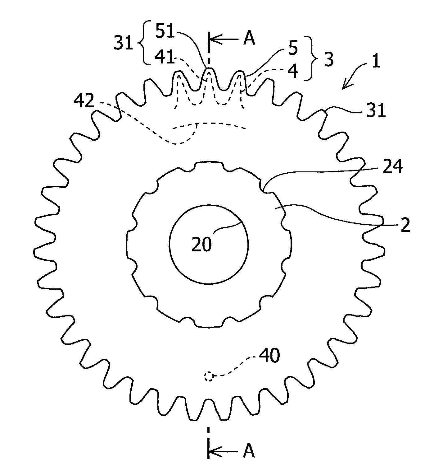
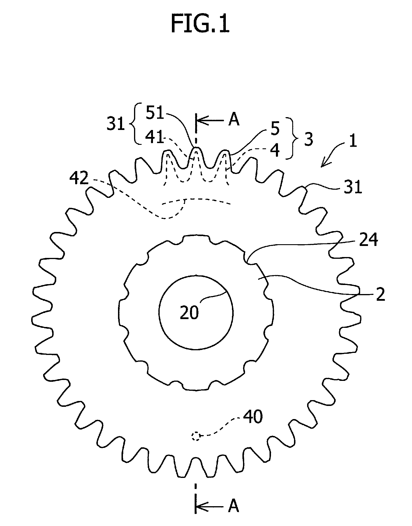
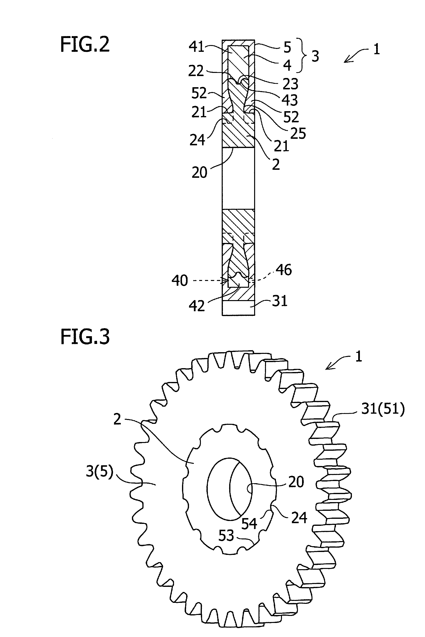
[0031]FIG. 1 is a side view showing a plastic gear 1 of the embodiment in which the present invention is implemented as a spur gear, FIG. 2 is its A-A cross sectional view, and FIG. 3 is a perspective view. In the drawings, the plastic gear 1 is constituted from a metal insert 2 (gear inner circumferential member) and a plastic portion 3 including tooth port...


PUM


Abstract

A plastic gear having a gear peripheral portion including a tooth portion is constituted by a plastic material, and a gear inner circumferential member with an annular shape or a disk shape is provided at the inner circumferential side of the gear peripheral portion. The gear peripheral portion includes an inner core and a surface layer member, the inner core being covered with the surface layer member and made of plastic with high elastic modulus and high strength, and the surface layer member being made of plastic with relatively low elastic modulus. The inner core is revolvably fitted around the gear inner circumferential member so as to revolve around the gear revolving axis, and an engaging portion is provided at an interface of the surface layer member and the gear inner circumferential member for preventing relative revolution around the gear revolving axis.

Description

CROSS REFERENCE TO RELATED APPLICATIONS[0001]This application claims the benefit of Japanese Patent Application No. 2006-340841, filed Dec. 19, 2006, which is incorporated herein by reference in its entirety and for all purposes.FIELD OF THE INVENTION[0002]The present invention relates to a plastic gear including an insert made of metal or the like and a plastic portion.BACKGROUND OF THE INVENTION[0003]In some cases, a steel gear has problems in which engaging noise caused by transmission error or tooth beating sound caused by backlash results in vibrations and noise. Compared with this, a plastic gear in which a portion of the gear tooth is formed from plastic, has a merit of possessing physical properties of viscoelastic behavior of the plastic, that is, large attenuation and low rigidity, and therefore, it is possible to complete the gear with low vibrations and low noise. Further, since the plastic gear is lightweight, and has the advantage that the plastic gear is obtained at l...

Claims


Application Information

Patent Timeline
Patent Type & Authority Patents(United States)
IPC IPC(8): F16H55/14
CPCF16H55/06F16H55/14F16H2055/065Y10T74/19623Y10T74/19907Y10T74/19898Y10T74/19633Y10T74/19967
Inventor SHINOHARA, RYUTARO
Owner SUZUKI MOTOR CORP
Why Eureka
Try Eureka