
Focus detector arrangement and method for generating contrast x-ray images

a detector arrangement and detector technology, applied in tomography, instruments, applications, etc., can solve the problems of high background noise, difficult to achieve dose rating, etc., and achieve the effect of improving the dose utilization rate of phase contrast imaging

Active Publication Date: 2010-10-19
SIEMENS HEALTHCARE GMBH
View PDF11 Cites 70 Cited by
  • Summary
  • Abstract
  • Description
  • Claims
  • Application Information

AI Technical Summary

Benefits of technology

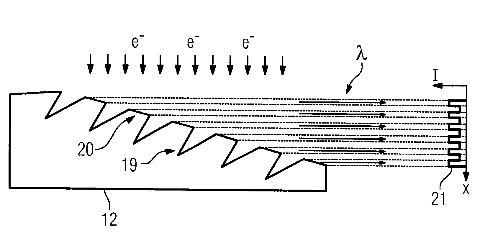
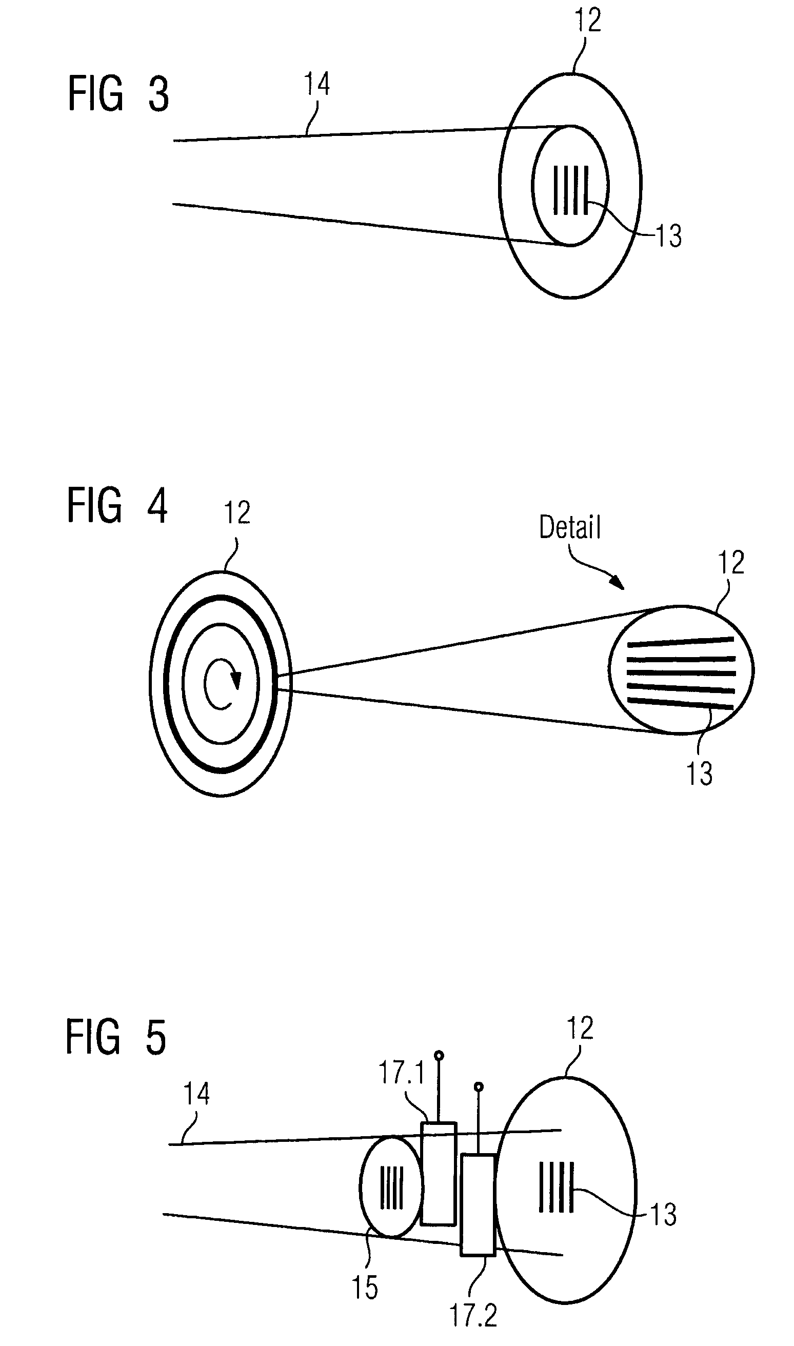
The present invention provides a focus detector arrangement for an x-ray apparatus that improves dose utilization for phase contrast imaging with sufficient dose rating for medical purposes. The ratio of radiation usable for phase contrast measurement to the radiation used for absorption measurements is improved. The arrangement includes a radiation source that generates a beam of coherent x-rays with a grid-like origin, a phase grid in the beam path of the x-rays on the examination subject, and an analysis-detector system that detects the interference pattern of the x-rays caused by the phase shift produced by tissue of the examination subject. The arrangement can also include an electron mask with band-like apertures between cathode and anode, an optoelectronic lens, and a rotary anode with bands arranged in a directional component axial to the rotation axis. The bands can exhibit a directional component axial to the rotation axis, and a matching unit can be provided to match the frequency and phase of the pulsation of the tube current. The arrangement can also include a conical anode surface and a rotary anode for better heat dissipation.

Problems solved by technology

This can be achieved by an extremely small focus, for example, but the achievable dose rating is barely usable for medical applications due to the long required exposure time.
Such applications are much too complicated in practice.
One problem given this type of focus detector combination is that, given the use of such source grids, a relatively high dose proportion nevertheless occurs that acts as quasi-coherent radiation, and therefore produces a high background noise and also leads to unnecessary radiation exposure of the examined patient.

Method used


Image

  • Focus detector arrangement and method for generating contrast x-ray images
  • Focus detector arrangement and method for generating contrast x-ray images
  • Focus detector arrangement and method for generating contrast x-ray images

Examples


Embodiment Construction

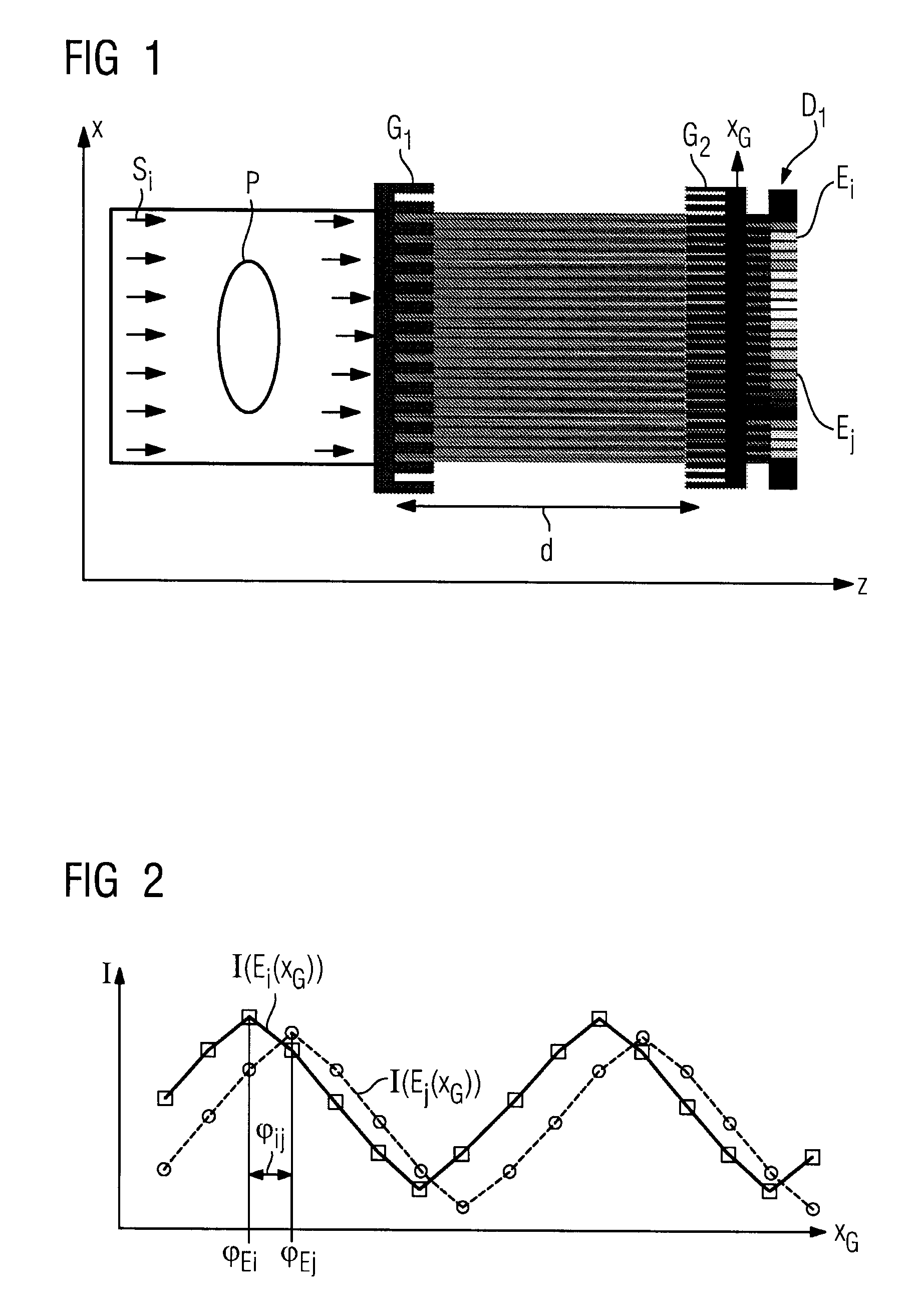
[0051]FIG. 1 shows a quasi-coherent radiation coming from a focus or individual coherent rays coming from a source grid that penetrate a probe P, wherein phase shift appearances of the probe P occur after the penetration. An interference pattern which is represented by the grey shading is hereby generated upon passage through the grid G1, which interference pattern (with the aid of the grid G2) leads to different radiation intensities per detector element on the subsequent detector D1 and its detector elements, wherein what is known as a Moiré pattern forms at what is known as a Talbot distance. If one considers the detector element E1 dependent on an offset xG of the analysis grid G2 and translates the intensity I(Ei(xG) as a function of the offset xG over intensity I, one obtains a sinusoidal rise and fall (shown in FIG. 2) of the intensity I at this detector element Ei. If these measured radiation intensities I for each detector element Ei or Ej are plotted dependent on the offse...


PUM

PropertyMeasurementUnit
angleaaaaaaaaaa
tomographic phase contrastaaaaaaaaaa
energyaaaaaaaaaa

Abstract

In a focus detector arrangement and method for an x-ray apparatus for generating projection or tomographic phase-contrast images of an examination subject, a beam of coherent x-rays is generated by an anode that has areas of different radiation emission characteristics arranged in bands thereon, that proceed parallel to grid lines of a phase grid that is used to generate the phase-contrast images.

Description

BACKGROUND OF THE INVENTION[0001]1. Field of the Invention[0002]The present invention concerns a focus detector arrangement of an x-ray apparatus for generation of projection or tomographic phase contrast exposures of an examination subject: of the type having a radiation source arranged on a first side of the examination subject, that generates a beam of coherent rays with grid-like origin, a phase grid arranged in the beam path on the opposite second side of the examination subject that generates an interference pattern of the x-ray radiation in a predetermined energy range of the x-ray radiation, and an analysis detector system that locally detects at least one interference pattern generated by the phase grid relative to its phase shift. The invention also concerns a method for generation of projection or tomographical x-ray phase contrast exposures with such a focus detector arrangement.[0003]2. Description of the Prior Art and Related Subject Matter[0004]Focus detector arrangem...

Claims


Application Information

Patent Timeline
Patent Type & Authority Patents(United States)
IPC IPC(8): G01N23/04
CPCA61B6/00A61B6/484A61B6/4291A61B6/032A61B6/4028A61B6/4441G21K2201/06G21K2207/005H01J2235/086
Inventor BAUMANN, JOACHIMDAVID, CHRISTIANENGELHARDT, MARTINFREUDENBERGER, JORGHEMPEL, ECKHARDHOHEISEL, MARTINMERTELMEIER, THOMASPFEIFFER, FRANZPOPESCU, STEFANSCHUSTER, MANFRED
Owner SIEMENS HEALTHCARE GMBH
Learn More